
Aktiv
PT-MA-HDBT42
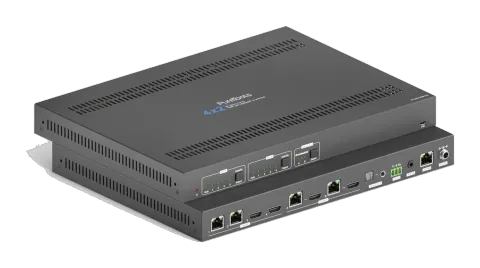
4x2 4K 18Gbps HDMI HDBaseT Matrix mit Scaler
Der 4x2 4K HDMI und HDBaseT Matrix Switcher PT-MA-HDBT42 ist ein Matrix Switcher mit zwei HDBaseT- und zwei HDMI-Eingängen, der Signale an zwei HDBaseT-Ausgänge verteilt, jeweils mit einem gespiegelten HDMI Loop-out. Er …
HandbuchSteuerbefehle (TCP/IP)FAQFirmwareCEVerfügbare Steuerschnittstellen. Klappen Sie einen aktiven Typ auf, um die vollständige Befehlstabelle zu sehen.
Keine passenden Befehle.
TCP/IP GUI Control11 BefehleAktiv
Quelle: Handbuch, Kapitel GUI Control, Seite 17
| Befehl | Beschreibung | Antwort | |
|---|---|---|---|
| Select input source 1~4 for output A | HDBT OUT A: Select input source 1~4 for output A. Click Auto to enable auto switching mode for output A. | ||
| Auto | Click Auto to enable auto switching mode for output A. | ||
| Select input source 1~4 for output B | HDBT OUT B: Select input source 1~4 for output B. Click Auto to enable auto switching mode for output B. | ||
| Auto | Click Auto to enable auto switching mode for output B. | ||
| Select HDBT OUT A de-embedded audio | Select HDBT OUT A de-embedded audio for SPDIF + Stereo audio outputs. | ||
| Turn on/off PoC for HDBT input 1~2 and HDBT output A~B | PoC Setting: Turn on or off PoC for HDBT input 1 and 2 and outputs A and B. | ||
| Modify the label of input sources | INPUTS: Modify input source labels. | ||
| Modify the label of presets | Preset: Modify preset labels. | ||
| Set command format to HEX or ASCII | Set format of RS232 commands to send. | ||
| Modify username and password | Security Tab: Modify login credentials. | ||
| Enable or disable automatic log-off mode | Security Tab function to set auto log-off. |
RS232 Befehle26 BefehleAktiv
VerbindungRS232 Kommunikationsprotokoll Baudrate: 9600 Datenbit: 8 Stoppbit: 1 Paritätsbit: keine↓ CSV
Quelle: Handbuch, Kapitel RS232 Communication Commands, Seite 40
| Befehl | Beschreibung | Beispiel | Antwort | |
|---|---|---|---|---|
| >SetPowerOn [param1] | Standby-Modus betreten/verlassen. [param1] = En, Dis En - Einschalten. Dis - Standby-Modus. | >SetPowerOn En >SetPowerOn Dis <PowerOn True | ||
| >GetFirmwareVersion | Abrufen der Firmware-Version. | <V1.0.0 | ||
| >SetFactoryReset | Auf Werkseinstellung zurücksetzen. | <FactoryReset_True | ||
| >SetReboot | Gerät neu starten. | <Reboot_True | ||
| >GetStatus | Betriebsstatus des Systems abrufen. | … | ||
| >SetRS232Baudrate [param1] | Stellen Sie die serielle Baudrate des Matrix Switchers auf [param1] ein. [param1] = 1~7 1- 115200 2 - 57600 3 - 38400 4 - 19200 5 - 9600 6 - 4800 7 - 2400 | >SetRS232Baudrate 3 <RS232Baudrate 9600 | ||
| >GetRS232Baudrate | Abrufen der Baudrate des Switchers. | <RS232Baudrate 9600 | ||
| >SetKeyboardLock [param1] | Vorderseitige Tasten sperren/entsperren. [param1] = En, Dis | >SetKeyboardLock En >SetKeyboardLock Dis | ||
| >GetKeyboardLock | Abrufen des Sperrstatus der Frontplatte. | <KeyboardLock False | ||
| >SetSignalDet [param1] | Legt die Methode zur Eingangssignalerkennung fest. [param1] = 5V, TMDS. | >SetSignalDet TMDS >SetSignalDet 5V <SignalDetMode 5V | ||
| >GetSignalDet | Ruft die Methode zur Eingangssignalerkennung ab. | <SignalDetMode 5V | ||
| >Set5VSource [param1] | Im Auto-Switching-Modus wird die Erkennungsmethode der HDBT-Eingänge festgelegt, um das Signal des Transmitters zu erkennen, damit verschiedene Transmitter verwendet werden können. [param1] = HW, FW. HW - Hardware-Erkennung. FW - Firmware-Erkennung. | >Set5VSource HW >Set5VSource FW <HDBTIN5VSourceFrom FW | ||
| >Get5VSource | Abrufen der Erkennungsmethode der HDBT-Eingänge zur Erkennung des Signals des Transmitters, um sicherzustellen, dass verschiedene Transmitter verwendet werden können. | <HDBTIN5VSourceFrom FW | ||
| >SetDownScaler [param1] [param2] | Legt die Downscaling-Funktion des Outputs [param1] fest. [param1] = OutA, OutB. [param1] = Null, alle Outputs. [param2] = En, Dis. En - Downscaling-Funktion aktivieren. Dis - Downscaling-Funktion deaktivieren. | >SetDownScaler En >SetDownScaler Dis <DownScaler False | ||
| >GetDownScaler [param1] | Abrufen des Downscaling-Funktionseinstellungsstatus von Ausgang [param1]. [param1] = OutA, OutB. [param1] = Null, alle Ausgänge. | >GetDownScaler <DownScaler False | ||
| >SetDhcp [param1] | DHCP (Dynamic Host Configuration Protocol) aktivieren/deaktivieren. [param1] = En, Dis. En - DHCP aktivieren. Dis - DHCP deaktivieren. | >SetDhcp En >SetDhcp Dis <Dhcp False | ||
| >GetDhcp | DHCP-Status abfragen. | <Dhcp False | ||
| >SetIpAddr [param1].[param2].[param3].[param4] | GUI-IP setzen. [param1] = 0 ~ 255. [param2] = 0 ~ 255. [param3] = 0 ~ 255. [param4] = 0 ~ 255. | >SetIpAddr 192.168.0.178 <SetIpAddr 192.168.0.178 | ||
| >GetIpAddr | GUI-IP abfragen. | <SetIpAddr 192.168.0.178 | ||
| >SetSubnetMask [param1].[param2].[param3].[param4] | Subnetzmaskenadresse der GUI einstellen. [param1] = 0 ~ 255. [param2] = 0 ~ 255. [param3] = 0 ~ 255. [param4] = 0 ~ 255. | >SetSubnetMask 255.255.255.0 <SetSubnetMask 255.255.255.0 | ||
| >GetSubnetMask | Ruft die Subnetzmaske der GUI ab. | <SetSubnetMask 255.255.255.0 | ||
| >SetGateWay [param1].[param2].[param3].[param4] | Legt die Gateway-Adresse der GUI fest. [param1] = 0 ~ 255. [param2] = 0 ~ 255. [param3] = 0 ~ 255. [param4] = 0 ~ 255. | >SetGateWay 192.168.0.1 <SetGateWay 192.168.0.1 | ||
| >GetGateWay | Abrufen der Gateway-Adresse der GUI. | <SetGateWay 192.168.0.1 | ||
| >SetPoCOut [param1] [param2] | PoC ein-/ausschalten. [param1] = IN1, IN2, OutA, OutB, Null. IN1 - HDBT Eingang 1. IN2 - HDBT Eingang 2. OutA - HDBT Ausgang A. OutB - HDBT Ausgang B. Null - alle HDBT Eingänge und Ausgänge. [param2] = En, Dis En - PoC einschalten. Dis - PoC ausschalten. | >SetPoCOut Dis >SetPoCOut En >SetPoCOut IN1 Dis >SetPoCOut IN1 En >SetPoCOut IN2 Dis >SetPoCOut IN2 En >SetPoCOut OutA Dis >SetPoCOut OutA En >SetPoCOut OutB Dis >SetPoCOut OutB En <PoCOut OutB On | ||
| >GetPoCOut [param1] | PoC-Einstellungsstatus abrufen. [param1] = IN1, IN2, OutA, OutB, Null. IN1 - HDBT Eingang 1. IN2 - HDBT Eingang 2. OutA - HDBT Ausgang A. OutB - HDBT Ausgang B. Null - alle HDBT Eingänge und Ausgänge. | >GetPoCOut >GetPoCOut IN1 >GetPoCOut IN2 >GetPoCOut OutA >GetPoCOut OutB <PoCOut OutB On | ||
| >SetAV [param1] [param2] | Wechsel Video Eingang [param2] auf Video Ausgang [param1]. [param1] = OutA, OutB. [param1] = Null, alle Ausgänge. [param2] = H1, H2, H3, H4 H1 - HDBT Eingang 1. H2 - HDBT Eingang 2. H3 - HDMI Eingang 3. H4 - HDMI Eingang 4. | >SetAV H1 >SetAV OutA H1 >SetAV OutB H1 <AV OutB H1 |
RS232-Befehle27 BefehleAktiv
Quelle: Handbuch, Kapitel Command Description, Seite 44
| Befehl | Beschreibung | Beispiel | Antwort | |
|---|---|---|---|---|
| >GetAV [param1] | Get input source for output [param1]. [param1] = OutA, OutB. [param1] = Null, all outputs. | >GetAV >GetAV OutA >GetAV OutB | <AV OutA H1 <AV OutB H1 | |
| >SetAutoSwitch [param1] [param2] | Enable/disable auto switching mode for output[param1]. [param1] = OutA, OutB. [param1] = Null, all outputs. [param2] = En, Dis En - Enable Dis - Disable | >SetAutoSwitch En >SetAutoSwitch Dis >SetAutoSwitch OutA En >SetAutoSwitch OutA Dis >SetAutoSwitch OutB En >SetAutoSwitch OutB Dis | <AutoSwitch OutA Enable <AutoSwitch OutA Disable <AutoSwitch OutB Enable <AutoSwitch OutB Disable | |
| >GetAutoSwitch [param1] | Get the auto switching mode setting of output[param1]. [param1] = OutA, OutB. [param1] = Null, all outputs. | >GetAutoSwitch >GetAutoSwitch OutA >GetAutoSwitch OutB | <AutoSwitch OutA Enable <AutoSwitch OutA Disable <AutoSwitch OutB Enable <AutoSwitch OutB Disable | |
| >SaveScreenMode [param1] | Aktuellen Umschaltstatus in Präsentation [param1] speichern. [param1] = 1~6. | >SaveScreenMode 1 <CallScreenMode 1 | ||
| >RecallScreenMode [param1] | Preset [param1] laden. [param1] = 1~6. | >RecallScreenMode 2 <CallScreenMode 2 | ||
| >ClearScreenMode [param1] | Setzt die aktuelle [param1] zurück. [param1] = 1~6. | >ClearScreenMode 2 <ClearScreenMode 2 | ||
| >SetAudioSrc [param1] | Set the audio source of SPDIF + Stereo audio outputs. [param1] = OutA, OutB OutA - Audio de-embedding from output A. OutB - Audio de-embedding from output B. | >SetAudioSrc OutA >SetAudioSrc OutB | <AudioSrc OutA De-embedded <AudioSrc OutB De-embedded | |
| >SetSpdif [param1] | SPDIF-Audioausgang stummschalten/aktivieren. [param1] = Mute, UnMute | >SetSpdif Mute >SetSpdif Unmute | <Spdif Mute <Spdif UnMute | |
| >SetIis [param1] | Stereo-(I2S)-Audioausgang stummschalten/aktivieren. [param1] = Mute, UnMute | >SetIis Mute >SetIis Unmute | <Iis Mute <Iis UnMute | |
| >GetAudioSta | Audio-Ausgangsstatus abrufen. | <AudioSrc OutA De-embedded <AudioSrc OutB De-embedded <Spdif Mute <Spdif UnMute <Iis Mute <Iis UnMute | ||
| >SetHdcpOutput [param1] [param2] | Set the HDCP mode of output. [param1] = OutA, OutB. [param1] = Null, all outputs. [param2] = Active, Passive, Off. Active - HDCP 1.4 Passive - Follows the HDCP of input signal, supports up to HDCP 2.2. Off - No HDCP content. | >SetHdcpOutput Active >SetHdcpOutput Passive >SetHdcpOutput Off | <HdcpOutput Active <HdcpOutput Passive <HdcpOutput Off | |
| >GetHdcpOutput | HDCP-Einstellungsstatus des Ausgangs abfragen. | <HdcpOutput Active <HdcpOutput Passive <HdcpOutput Off | ||
| >SetUpdateEdid [param1] | Upload a user-defined EDID. The EDID can be saved for invoking at any time. When the command is applied, system prompts to upload the EDID file (.bin). Operation will be cancelled in 10 seconds. [param1] = 1, 2. 1 - Upload user-defined EDID 1. 2 - Upload user-defined EDID 2. | >SetUpdateEdid 1 | <User 1 EDID Ready Please Send EDID Data Within 10 Seconds | |
| >SetEdidMode [param1] [param2] | Set the EDID of input. [param1] = H1, H2, H3, H4, Null H1 - HDBT input 1. H2 - HDBT input 2. H3 - HDMI input 3. H4 - HDMI input 4. Null - All inputs. [param2] = 1~12 1 - HDBT OUTA EDID Copy 2 - HDBT OUTB EDID Copy 3 - 1920x1080@60Hz 8bit Stereo 4 - 1920x1080 8bit High Definition Audio 5 - 3840x2160@30Hz 8bit Stereo Audio 6 - 3840x2160@30Hz Deep Color High Definition Audio 7 - 3840x2160@60Hz 4:2:0 Deep Color Stereo Audio 8 - 3840x2160@60Hz Deep Color Stereo Audio 9 - 3840x2160@60Hz Deep Color High Definition Audio 10 - 3840x2160@60Hz Deep Color HDR LPCM 6CH 11 - user-defined EDID 1 12 - user-defined EDID 2 | >SetEdidMode 8 >SetEdidMode H1 8 >SetEdidMode H2 8 >SetEdidMode H3 8 >SetEdidMode H4 8 | <EDIDMode H1 8 <EDIDMode H2 8 <EDIDMode H3 8 <EDIDMode H4 8 | |
| >GetEdidMode [param1] | Get the EDID of input. [param1] = H1, H2, H3, H4, Null H1 - HDBT input 1. H2 - HDBT input 2. H3 - HDMI input 3. H4 - HDMI input 4. Null - All inputs. | >GetEdidMode >GetEdidMode H1 >GetEdidMode H2 >GetEdidMode H3 >GetEdidMode H4 | <EDIDMode H1 8 <EDIDMode H2 8 <EDIDMode H3 8 <EDIDMode H4 8 | |
| >SetSrcCecControl [param1] [param2] | Send CEC command to control source device. [param1] = H1, H2, H3, H4, Null H1 - HDBT input 1. H2 - HDBT input 2. H3 - HDMI input 3. H4 - HDMI input 4. Null - All inputs. [param2] = 1~18 1 - Volume- 2 - Menu 3 - Volume+ 4 - Back 5 - Up 6 – Enter 7 - Left 8 – Down 9 - Right 10 – On 11 - Off 12 - Stop 13 - Previous 14 – Next 15 - Pause 16 – REW 17 - FF 18 - Play | >SetSrcCecControl H1 1 >SetSrcCecControl H2 1 >SetSrcCecControl H3 1 >SetSrcCecControl H4 1 | <SourceCECCommand H1 1 <SourceCECCommand H2 1 <SourceCECCommand H3 1 <SourceCECCommand H4 1 | |
| >SetDisCecControl [param1] [param2] | Send CEC command to control display device. [param1] = OutA, OutB. [param1] = Null, all outputs. [param2] = 1~6 1 - On 2 - Off 3 - Source 4 - Mute 5 - Volume- 6 - Volume+ | >SetDisCecControl OutA 1 >SetDisCecControl OutB 1 | <DisplayCECCommand OutA 1 <DisplayCECCommand OutB 1 | |
| >SetUserCecControl [param1] [param2] | Customize CEC command to control source or display device. [param1] = 1~6 1 - HDBT input 1. 2 - HDBT input 2. 3 - HDMI input 3. 4 - HDMI input 4. 5 - HDBT output A. 6 - HDBT output B. [param2] = XX:XX......(HEX) | >SetUserCecControl 5 40:36 | <UserCECCommand 1 XX:XX…... | |
| >SetRS232Mode [param1] | Set the RS232 mode. [param1] = 1~4 1 - Local Control. 2 - HDBT Transmitter Pass Through 3 - HDBT Receiver Pass Through 4 - Pass Through Between Transmitter and Receiver. Note: The RS232 mode can be set by GUI RS232 tab. | >SetRS232Mode 1 >SetRS232Mode 2 >SetRS232Mode 3 >SetRS232Mode 4 | <RS232Mode 1 <RS232Mode 2 <RS232Mode 3 <RS232Mode 4 | |
| >GetRS232Mode | RS232-Steuermodus abrufen. | <RS232Mode 2 | ||
| >SetOn_[param1]_[param2]:[param3] | When the switcher is powered on, it automatically sends the saved RS232 command to control the far-end third-party devices. [param1] = A, H. A - ASCII command format. H - HEX command format. [param2] = 1~7 (Baud rate) 1 - 115200 2 - 57600 3 - 38400 4 - 19200 5 - 9600 6 - 4800 7 - 2400 [param3] = ASCII string or HEX string. (e.g. The string is used to turn on display device) Note: The command does not need command ending “ ”. | >SetOn_A_1:abc123 | <SetOn_Ascii (Baud)115200 abc123 | |
| >SetOff_[param1]_[param2]_[param3]:[param4] | When the switcher is powered off, it automatically sends the saved RS232 command to control the far-end third-party devices. [param1] = A, H. A - ASCII command format. H - HEX command format. [param2] = 1~7 (Baud rate). 1 - 115200 2 - 57600 3 - 38400 4 - 19200 5 - 9600 6 - 4800 7 - 2400 [param3] = 1, 2 1 - Send the RS232 string once. 2 - Send the RS232 string two times. [param4] = ASCII string or HEX string. (e.g. The string is used to turn off display device) Note: The command does not need command ending “ ”. | >SetOff_A_1_2:abc123 | SetOff_Ascii (Baud)115200 (Repeat)2 abc123 | |
| >SetOffRptDly [param1] | When the above Off RS232 command is set to be repeated 2 times, the interval between the two commands can be set by this command. [param1] = 300-10000 (ms) | >SetOffRptDly 300 | <OffRptDly 300 | |
| >GetOffRptDly | Ruft das Sendeintervall zwischen zwei Off-RS232-Befehlen ab. | <OffRptDly 300 | ||
| >Send_A_[param1]_[param2]:[param3] | Send ASCII command to the desired RS232 port. [param1] = 1~5 1 - Local 2 - HDBT input 1 3 - HDBT input 2 4 - HDBT output A. 5 - HDBT output B. [param2] = 1~7 (Baud rate) 1 - 115200 2 - 57600 3 - 38400 4 - 19200 5 - 9600 6 - 4800 7 - 2400 [param3] = ASCII string. Note: The command does not need command ending “ ”. | >Send_A_1_1:abc123 … | ||
| >Send_H_[param1]_[param2]:[param3] | Send HEX command to the desired RS232 port. [param1] = 1~5 1 - Local 2 - HDBT input 1 3 - HDBT input 2 4 - HDBT output A. 5 - HDBT output B. [param2] = 1~7 (Baud rate) 1 - 115200 2 - 57600 3 - 38400 4 - 19200 5 - 9600 6 - 4800 7 - 2400 [param3] = HEX string Note: The command does not need command ending “ ”. | >Send_H_1_1:31 32 33 … | ||
| >SetDisplayOn [param1] [param2] | Turn on/off the display devices by simultaneously sending CEC command and the saved RS232 command. [param1] = OutA, OutB. [param1] = Null, all outputs. [param2] = En, Dis En - Turn on display devices. Dis - Turn off display devices. | >SetDisplayOn En >SetDisplayOn Dis >SetDisplayOn OutA En >SetDisplayOn OutA Dis >SetDisplayOn OutB En >SetDisplayOn OutB Dis | <Display OutA Off <Display OutA On <Display OutB Off <Display OutB On |