
Safety precautions
To ensure the best from the product, please read all instructions carefully before using the device. Save this manual for further reference. Unpack the equipment carefully and save the original box and packing material for possible future shipment. Follow basic safety precautions to reduce the risk of fire, electrical shock and injury to persons.
- Do not dismantle the housing or modify the module. It may result in electrical shock or burn.
- Using supplies or parts not meeting the products’ specifications may cause damage, deterioration or malfunction.
- To prevent fire or shock hazard, do not expose the unit to rain, moisture or install this product near water.
- Do not remove the housing of the device as opening or removing housing may expose you to dangerous voltage or other hazards.
- Spillage into the housing may result in fire, electrical shock, or equipment damage. If an object or liquid falls or spills on to the housing, unplug the module immediately.
- Do not twist or pull by force ends of the optical cable. It can cause malfunction.
- Do not use liquid or aerosol cleaners to clean this unit. Always unplug the power to the device before cleaning.
- Information on disposal for scrapped devices: do not burn or mix with general household waste, please treat them as normal electrical wastes.
- Unplug the power cord when left unused for a long period of time.
- Keep the module away from liquids.
- Install the device in a place with fine ventilation to avoid damage caused by overheat.
- Do not put any heavy items on the extension cable in case of extrusion.
- Refer all servicing to qualified service personnel.
Product Introduction
Introduction
Features
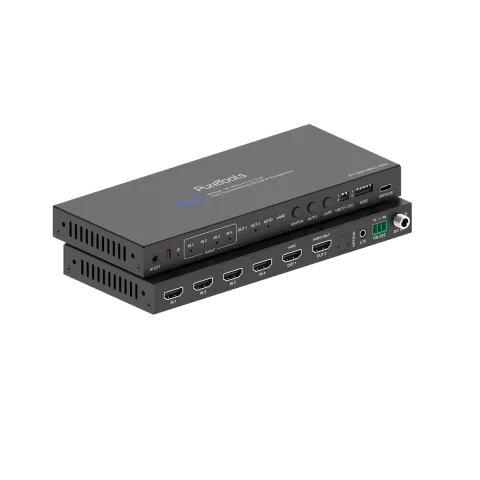
This 8K HDMI 4×1 Switcher allows you to connect 4 HDMI sources to 1 TV to output. The video resolutions is up to 8K@60Hz 4:2:0 12bit or 4K@120Hz 4:4:4 12bit. Audio de-embedding is supported for an AV receiver or a soundbar, in audio format such as Dolby Atmos, DTS-HD. In addition, analog stereo sound or digital 2.0/5.1 audio can be transmitted to headphones or active speakers.
- HDCP 2.3 compliant
- Supports 48Gbps FRL and 18Gbps TMDS video bandwidth
- HDMI 2.1 protocols: VRR, ALLM, QMS, QFT, SBTM are supported
- Supports HDR, HDR10, HDR10+, Dolby Vision, HLG pass-through
- Supports audio formats: LPCM 7.1CH, Dolby TrueHD, Atmos, DTS-HD Master, DTS:X Audio pass-through
- Advanced EDID management
- Supports auto input switching
- Supports CEC control from TV at output to source at input
- Supports CEC volume control from TV to any HDMI sound system
- Supports TV eARC audio and de-embedding audio from HDMI inputs to output HDMI, Optical and L/R audio
- Supports video resolution up to 8K@60Hz 4:2:0 12bit, 4K@120Hz 4:4:4 12bit, as specified in HDMI 2.1
Package List
- 1× 8K HDMI 4x1 Switcher with audio de-embedding
- 1× 5V/2A Multinational Locking Power Supply with USB Plug
- 1× EU Conversion Plug
- 1× IR Remote
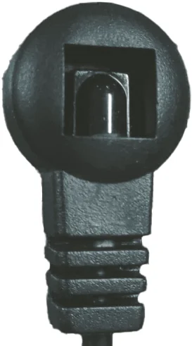
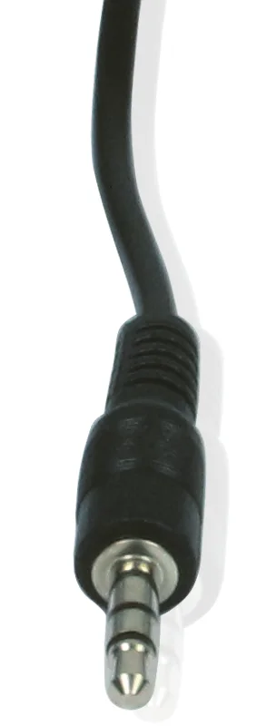
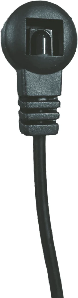
- 1× IR Receiver Cable (1.5m)
- 1× 3pin-3.5mm Phoenix Connector (male)
- 2× Mounting Ear
- 4× Machine Screw (KM3*4)
- 1× User Manual
Panel Description
| No. | Name | Function Description |
|---|---|---|
| 1 | IR EXT | IR signal receiving port, connected with IR Receiver cable. If the IR signal receiving window of the unit is blocked or the unit is installed in a closed area out of infrared line of sight, the IR receiver cable can be inserted to the “IR EXT” port to receive the IR remote signal. |
| 2 | IR window | IR signal receiving window. |
| 3 | Power LED | When the device is powered on, the power LED is green; When the device is standby, the power LED is red. |
| 4 | INPUT LED (1~4) | When IN 1/2/3/4 is selected as the input channel, the corresponding green LED is on. |
| 5 | OUT 1 LED | When a TV or displayer is connected to the OUT 1 port, the green LED will be on. |
| 6 | OUT 2 LED | When an audio device is connected to the OUT 2 port, the green LED will be on. |
| 7 | AUTO LED | When the auto switching is enabled, the LED will be on. |
| 8 | eARC LED | On: eARC function is working properly. Blinking: eARC function is not working properly. Off: eARC function is disabled. |
| 9 | SWITCH button | Press to switch IN 1/2/3/4 circularly as an input channel. |
| 10 | AUTO button | Press to enable or disable the auto switching function. |
| 11 | eARC button | Press to enable or disable the eARC function. |
| 12 | HDCP DIP switch | Use this DIP switch to set HDCP. 1 - Pass-through mode: The output HDCP follows the source. 0 - Managed mode: If the source has HDCP, the output will be set to HDCP 1.4; if the source has no HDCP, the output will be set to no HDCP. |
| 12 | CEC DIP switch | Use this DIP switch to enable or disable CEC. 1 - CEC disabled: Prevent CEC communication between source and sink devices. 0 - CEC enabled: Allow CEC communication between source and sink devices. |
| 12 | EDID DIP switch | Use the DIP switch to set EDID. [DIP]=11111: Copy OUT1 port sink EDID [DIP]=11110: FRL12G_8K_HDR, 2.0CH [DIP]=11101: FRL12G_8K_HDR, 5.1CH [DIP]=11100: FRL12G_8K_HDR, 7.1CH |
| 13 | EDID DIP switch (Continued) | [DIP]=11011: FRL10G_8K_HDR, 2.0CH [DIP]=11010: FRL10G_8K_HDR, 5.1CH [DIP]=11001: FRL10G_8K_HDR, 7.1CH [DIP]=11000: 5K60(444)_HDR, 2.0CH [DIP]=10111: 5K60(444)_HDR, 5.1CH [DIP]=10110: 5K60(444)_HDR, 7.1CH [DIP]=10101: 4K144(444), 2.0CH [DIP]=10100: 4K120(444), 2.0CH [DIP]=10011: 4K120(444), 5.1CH [DIP]=10010: 4K120(444), 7.1CH [DIP]=10001: 4K120(420)_HDR, 2.0CH [DIP]=10000: 4K120(420)_HDR, 5.1CH [DIP]=01111: 4K120(420)_HDR, 7.1CH [DIP]=01110: 4K60(444)_HDR, 2.0CH [DIP]=01101: 4K60(444)_HDR, 5.1CH [DIP]=01100: 4K60(444)_HDR, 7.1CH [DIP]=01011: UWQHD 120(444), 2.0CH [DIP]=01010: UWQHD 60(444), 2.0CH [DIP]=01001: 1440p120(444), 2.0CH [DIP]=01000: 1440p60(444), 2.0CH [DIP]=00111: 1080P240(444)_HDR, 2.0CH [DIP]=00110: 1080P144(444)_HDR, 2.0CH [DIP]=00101: 1080P120(444)_HDR, 2.0CH [DIP]=00100: 1080P60(444), 2.0CH [DIP]=00011: 1080P60(444), 5.1CH [DIP]=00010: 1080P60(444), 7.1CH [DIP]=00001: 1080P30(444), 2.0CH [DIP]=00000: Custom EDID Upload |
| No. | Name | Function Description |
|---|---|---|
| 14 | SERVICE | Firmware update port. |
| 15 | IN port (1~4) | HDMI signal input port, connected to an HDMI source device such as PC or PS5 with HDMI cable. |
| 16 | OUT1 port (eARC) | HDMI output port, connected to an HDMI display device such as TV with eARC function. |
| 17 | OUT2 port (AUDIO ONLY) | HDMI audio output port, connected to an audio device such as soundbar or amplifier. |
| 18 | OPTICAL | Optical fiber audio output port, connected to an audio output device such amplifier. |
| 19 | L/R | Analog audio output port, connected to an audio output device such as speaker. |
| 20 | RS-232 | 3-pin phoenix connector, connected to a PC or control system for serial command control. Note: RS-232 control must add CR/LF. |
| 21 | DC 5V | DC 5V/2A power input port. |
Auto Switching
The auto switching function can be enabled/disabled via the AUTO button on the front panel, IR remote or the RS-232 commands. It is enabled by default.
Restore Factory Defaults
Press and hold the Switch and eARC buttons for 3 seconds simultaneously to reset this switcher. At this time, all LEDs (except for the power LED) on the front panel are flashing twice. After completed, all setting are restored to factory defaults.
There are two auto switching modes: TMDS detection and 5V detection. And the default is TMDS detection. It can be set via RS-232 commands.
TMDS detection
- If an IN port is connected, it will switch to the port when the TMDS/FRL signal is detected, and the corresponding LED will light up.
- If the current input port is disconnected or in standby mode, and no signal is detected, it will switch to the next active port automatically. If there are no other active ports, it will stay at the current port.
5V detection
- If one IN port is connected, and the others are connected later. It will switch to the lastest one automatically (last in gets priority) as the input channel, and the corresponding LED will light up.
- If the four IN ports are connected meanwhile, when one of them is disconnected, it will switch to the next IN port automatically according to the order of IN 1~4.
- If only one IN port is connected, it will not automatically switch to the others when disconnected.
IR Remote
Power
Press this button to power on the switcher or set it to standby mode.
IR Receiver
Receives IR Signal.
Input Switching
Press this button to circularly switch the HDMI signal source from IN1 to IN4.
eARC:
Press this button to enable or disable the eARC function.
Auto:
Press this button to enable or disable the auto switching function.
1/2/3/4:
Press to switch the corresponding input channel.
IR Receiver
Specification
| Technical | |
|---|---|
| HDMI Compliance | HDMI 2.1 |
| HDCP Compliance | HDCP 2.3 |
| Video Bandwidth | 48Gbps |
| Video Resolution | Up to 8K@60Hz 4:2:0 12bit, 4K@120Hz 4:4:4 12bit |
| Color Depth | 8/10/12-bit |
| Color Space | RGB, YCbCr_4:4:4, YCbCr_4:2:2, YCbCr_4:2:0 |
| HDR | HDR, HDR10, HDR10+, Dolby Vision, HLG |
| IR Level | 5Vp-p |
| IR Frequency | Fixed frequency 38KHz |
| Audio Latency | No Latency |
| Video Latency | No Latency |
| Audio Format | HDMI input/output: LPCM, Dolby Digital/Plus/EX, Dolby True HD, Dolby Atmos, DTS, DTS-EX, DTS-96/24, DTS High Res, DTS-HD Master Audio, DSD Audio, DSD Audio de-embedding output: Optical: LPCM/Dolby/DTS 5.1CH Analog: LPCM 2CH |
| ESD Protection | IEC 61000-4-2: ±8kV (air-gap discharge) & ±4kV (contact discharge) |
| Connection | |
| Input | 4× IN [HDMI type A, 19-pin female] |
| Output | 2× OUT [HDMI type A, 19-pin female] 1× OPTICAL [S/PDIF] 1× L/R [3.5mm stereo mini-jack] |
| Control | 1× SERVICE [USB type C, upgrade port] 1× RS-232 [3pin-3.5mm phoenix connector] |
| Mechanical | |
| Housing | Metal Enclosure |
| Color | Black |
| Dimensions | 200mm [W] × 84mm [D] × 20mm [H] |
| Weight | 430g |
| Power Supply | DC 5V/2A |
| Power Consumption | 3.15W (Max) |
| Operation Temperature | 32 ~ 104°F / 0 ~ 40°C |
| Storage Temperature | -4 ~ 140°F / -20 ~ 60°C |
| Operating Humidity | 20%~80% relative humidity, non-condensing |
| Storage Humidity | 10%~90% relative humidity, non-condensing |
Recommended HDMI Cable
| Video Resolution | 8K | 4K60 | 1080P |
|---|---|---|---|
| HDMI Cable Length (HDMI IN / OUT) | 2m/6.6ft (Ultra HDMI 2.1) | 5m/16.4ft | 10m/32.8ft |
Note: The use of “Premium High Speed HDMI” cable is highly recommended.
API Commands
The product also supports RS-232 command control. Connect the RS-232 port of the PT-SW-HD41-48G to the appropriate cable and your control device. Then open a Serial Command tool on PC to send ASCII commands to control the product. The ASCII command list of the product is shown below.
(Note: RS-232 control must add CR/LF.)
Serial port protocol: baud rate: 115200 (default) Data bits: 8 Stop bits: 1 Check bit: 0
x - Parameter 1. y - Parameter
| Command | Function | Example | Feedback | Default |
|---|
System Setting
| help! | List all commands | help! | |
|---|---|---|---|
| r type! | Get device model | r type! | 8K 4x1 HDMI switcher |
| r info! | Get device current status | r info! | current unit status: mcu fw version: Vx.xx.xx power status: on hdmi input1: disconnect hdmi input2: disconnect hdmi input3: disconnect hdmi input4: disconnect hdmi output1: disconnect hdmi output2: disconnect connection route: input1->output1 output 1 hdcp: user mode on hdcp dip mode: hdcp follow source cec dip mode: cec off auto switch: on earc mode: off auto switch mode: TMDS mode input edid mode: copy from output |
| r fw version! | Get Firmware version | r fw version! | MCU FW version x.xx.xx |
| power z! | Power on/off the device, z=0~1 (z=0 power off, z=1 power on) | power 1! | power on System Initializing... Initialization Finished! MCU FW version x.xx.xx |
| r power! | Get current power state | r power! | power on /power off |
| r temperature! | get temperature | r temperature! | gsv chip temperature: 47 |
| reboot! | Reboot the device | reboot! | Reboot… System Initializing... Initialization Finished! MCU FW version x.xx.xx |
| reset! | Reset to factory defaults | reset! | Reset to factory defaults System Initializing... Initialization Finished! MCU FW version x.xx.xx |
Input/Output Setting
| s user edid! | Upload local edid | s user edid! | Please send the edid file… edid: 1080P60, Audio 2.0CH |
|---|---|---|---|
| r input edid! | Get input edid mode | r input edid! | input edid: 4K2K60_444, Stereo Audio 2.0 |
| s auto switch x! | Enable/disable auto switch feature (x=0~1) 0. Disable auto switch 1. Enable auto switch | s auto switch 0! | auto switch off auto switch: on |
| r auto switch! | Get auto switch feature | r auto switch! | auto switch: on |
| s auto mode x! | set auto switch mode(x=0~1) 0.TMDS mode 1.5V mode | s auto mode 1! | auto switch mode: 5v mode auto switch mode: TMDS mode! |
| r auto mode! | get auto switch mode | r auto switch! | auto switch mode: TMDS mode |
| s earc x! | Enable/disable Earc function (x=0~1) 0. earc off 1. earc on | s earc 0! | earc off earc off |
| r earc! | Get earc feature | r earc! | earc off |
| s in source x! | Route input source to output (1~4) 1. HDMI 1 2. HDMI 2 3. HDMI 3 4. HDMI 4 | s in source 1! | output->input1 input 1 |
| r in source! | Get output selected input source | r in source! | output->input1 |
| s output hdcp x! | set user mode on/off (x=0~1) | s output hdcp 0! | output: user mode on user mode off |
| r output hdcp! | get output hdcp status | r output hdcp! | output: user mode off |
| s baud rate z! | set rs232 serial port baud rate (z=115200, 57600, 38400, 19200, 9600, 4800, 2400) | s baud rate 115200! | set the baud rate to 115200 baud rate: 115200 |
System Diagram
The following diagrams illustrate typical input and output connections that can be utilized with this device:
Note: The terms HDMI and HDMI High-Definition Multimedia interface, and the HDMI Logo are trademarks or registered trademarks of HDMI Licensing LLC in the United States and other countries.
- Line Level Audio Device
- AVR or Amplifier
- 8K TV with eARC
- Power Supply
- PC
- IR Receiver
- Soundbar
1 4 2 3 AutoeARC
Usage Precaution
- Make sure all components and accessories included before installation.
- System should be installed in a clean environment with proper temperature and humidity.
- All of the power switches, plugs, sockets, and power cords should be insulated and safe.
- All devices should be connected before power on.
Firmware Upgrade
Please follow the steps as below to upgrade firmware by the Service port on the front panel:
- Prepare the PC tool (.exe) and the latest upgrade file (.bin) on PC. Rename the upgrade file as “MCU_MAIN_PT-SW-HD41-48G_Vxx.xx.xx.bin”.
- Connect the Service port on the splitter to the PC with USB cable.
- Connect the power supply to the splitter and power on.
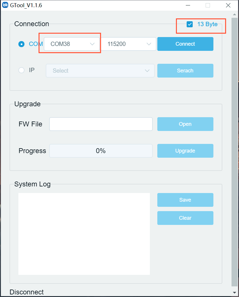
- Click the channel on PC, check "13 Byte", and then click “Connect”. Search
Search
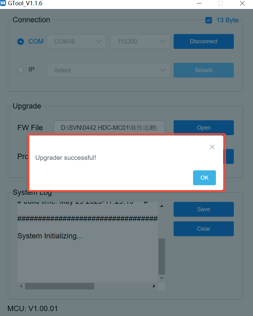
- Click "Open" to select the upgrade file MCU_Main_PT-SW-HD41-48G_Vxx.xx.xx.bin, then click "Upgrade".
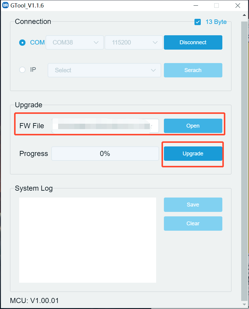
- When the upgrade is completed, it will pop up "Upgrade successful!". If the firmware updating is fail, the name of upgrade file (.bin) should be confirmed, and then follow the above steps to update again.
- Remove the USB cable after firmware upgrade.
After-Sales Service
If there appear some problems when running the product, please check and deal with the problems referring to this user manual. Any transport costs are borne by the users during the warranty.
- Product Limited Warranty: This product will be free from defects in materials and workmanship for three years (The purchase invoice shall prevail). Proof of purchase in the form of a bill of sale or receipted invoice which is evidence that the unit is within the Warranty period must be presented to obtain warranty service.
- What the warranty does not cover (servicing available for a fee):
- Warranty expiration.
- Factory applied serial number has been altered or removed from the product.
- Damage, deterioration or malfunction caused by:
- Normal wear and tear.
- Use of supplies or parts not meeting our specifications.
- No certificate or invoice as the proof of warranty.
- The product model showed on the warranty card does not match with the model of the product for repairing or had been altered.
- Damage caused by force majeure.
- Servicing not authorized by distributor.
- Any other causes which does not relate to a product defect.
- Delivery, installation or labor charges for installation or setup of the product.
- Technical Support: For any questions or problems, contact your distributor or reseller and tell them the respective product name and version, the detailed failure situation as well as the formation of the cases.
Asking for Assistance
Technical Support
Technical Support Hours
8:30 AM to 5:00 PM Monday thru Thursday
8:30 AM to 4:00 PM Friday
Write to
PureLink GmbH
Von-Liebig-Straße 10
D - 48432 Rheine
Phone: +49 5971 800299 - 0
Fax: +49 5971 800299 – 99
Legal & Compliance
Product identification
Model: PT-SW-HD41-48G – manual version 1.0
Trademarks and disclaimer
Product model and logo are trademarks. All other company and product names mentioned are trademarks of their respective owners. All rights reserved. No part of this publication may be copied or reproduced without prior written permission. We reserve the right to make changes to the device, packaging or manual and accept no liability for misprints.
EU conformity
PureLink hereby declares that this product PureTools PT-SW-HD41-48G complies with Directives 1907/2006/EU und 2011/65/EU. PureLink GmbH hereby declares that this product PureTools PT-SW-HD41-48G complies with Directives 2014/30/EU and 2014/35/EU.
| Directive / Regulation |
|---|
| 1907/2006/EU |
| 2011/65/EU |
| 2014/30/EU |
| 2014/35/EU |
The full text of the EU Declaration of Conformity is available at: www.purelink.de
FCC
FCC FCC FCC FCC Statement It has been tested and found to comply with the limits for a Class B digital device, pursuant to part 15 of the FCC Rules.
Disposal of electrical and electronic equipment
WEEE reg. no.: DE 93847290
The crossed-out wheelie bin symbol on the product, packaging or in this manual means that electrical and electronic equipment must not be disposed of with household waste at the end of its life. Hand in old devices free of charge at a public collection point or return them to a distributor obliged to take them back. Remove batteries and lamps that can be removed without destroying the device before handing it in, and delete any personal data stored on the device. Details are regulated by national law. By returning old devices you help protect the environment.
Batteries
Batteries must not be disposed of with household waste. Return used batteries free of charge to collection points or retailers.
Packaging
Dispose of packaging separately by material (paper/cardboard, plastics) via the local collection systems. Keep packaging material away from children – risk of suffocation. Packaging register LUCID: DE5958616449295.