
Safety precautions
- Unpack the equipment carefully and save the original box and packing material for possible future shipment
- Follow basic safety precautions to reduce the risk of fire, electrical shock and injury to persons.
- Do not dismantle the housing or modify the module. It may result in electrical shock or burn.
- Using supplies or parts not meeting the products’ specifications may cause damage, deterioration or malfunction.
- Refer all servicing to qualified service personnel.
- To prevent fire or shock hazard, do not expose the unit to rain, moisture or install this product near water.
- Do not put any heavy items on the extension cable in case of protrusion.
- Do not remove the housing of the device as opening or removing the housing may expose you to dangerous voltage or other hazards.
- Install the device in a place with sufficient ventilation to avoid damage caused by overheat.
- Keep the module away from liquids.
- Spillage into the housing may result in fire, electrical shock, or equipment damage. If an object or liquid falls or spills on to the housing, unplug the module immediately.
- Do not twist or pull by force ends of the optical cable. It can cause malfunction.
- Do not use liquid or aerosol cleaners to clean this unit. Always unplug the power to the device before cleaning.
- Unplug the power cord when left unused for a long period of time.
- Information on disposal for scrapped devices: do not burn or mix with general household waste, please treat them as normal electrical wastes.
Product Introduction
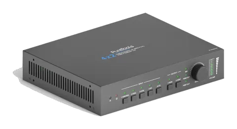
Thanks for choosing the professional 4x2 HDMI 2.0 presentation switcher with an HDBaseT receiver. The switcher is designed to switch HDMI or DP video signal to HDMI and HDBaseT output. It provides three HDMI inputs, one DP input, one HDMI output and one HDBaseT output. The HDBaseT output supports PoC and can connect compatible HDBaseT receiver up to a maximum of 70 meters (230 feet).
The switcher supports input video resolution up to 4Kx2K@60Hz 4:4:4. With multiple built-in EDID settings, including an EDID pass-through option, the highest quality digital video signal will be routed directly to the display.
The switcher supports stereo and multichannel audio on the HDMI or DP input. In addition to the audio embedded in the HDMI and HDBT output stream, which may be muted, the audio is simultaneously de-embedded to an analog audio output.
The switcher features multiple methods of control. When set to Auto, the switcher will automatically switch to the newest source device added to the switcher; when the active source is removed, the switcher will switch to the first detected input. The switcher can be manually controlled by front panel buttons, IR, RS232, and GUI.
Features
- The transmission distance between the switcher and the HDBaseT receiver can range up to 70m for 1080p and 40m for 4K video.
- Supports automatic switching.
- HDMI and DP video resolution up to 4Kx2K@60Hz 4:4:4.
- Supports HDMI 2.0, HDCP 2.2 compliant.
- Supports DP 1.2 and Multi-Stream Transport (MST).
- The MIC and LINE input can be mixed to audio outputs.
- 3-type microphone input, supports condenser microphone, dynamic microphone and wireless microphone.
- Smart EDID management: Four built-in preset EDIDs for various applications and customized setting allowed.
- Supports 12V PoC.
- Controllable by front panel buttons, IR remote, RS232 and GUI.
- Supports firmware upgrade.
Package List
HDMI 2.0 Presentation Switcher
- 1x PT-PMS-42 4x2 4K Presentation Switcher
- 2x Mounting Ears with 4 Screws
- 4x Plastic Cushions
- 1x IR Receiver
- 1x IR Emitter
- 1x IR Remote
- 2x 3-pin Terminal Blocks
- 1x 5-pin Terminal Block
- 1x Power Adaptor (24V DC 2.71A)
HDBaseT Receiver
- 1x PT-HDBT-200-RX HDBaseT Receiver
- 2x Mounting Ears with 2 Screws
- 4x Plastic Cushions
- 1x 3-pin Terminal Block
- 1x User Manual
Note: Please contact your distributor immediately if any damage or defect in the components is found.
x2 4K Presentation Switcher
| Video | |
|---|---|
| Video Input | (1) HDMI/MHL, (3) HDMI, (1) DP |
| Video Input Connector | (3) Type-A female HDMI, (1) DisplayPort |
| HDMI Input Resolution | Up to 4Kx2K@60Hz 4:4:4 8bit |
| MHL Input Resolution | Up to 1080P@60Hz |
| DP Input Resolution | Up to 4Kx2K@60Hz 4:4:4 8bit |
| Video Output | (1) HDMI, (1) HDBT |
| Video Output Connector | (1) Type-A female HDMI, (1) RJ45 |
| HDMI Output Resolution | Up to 4Kx2K@60Hz 4:4:4 8bit |
| HDBT Output Resolution | Up to 4Kx2K@60Hz 4:2:0 8bit |
| HDMI Version | 2.0 |
| HDCP Version | 2.2 |
| MHL Version | 2.2 |
| DP Version | 1.2 |
| HDR | Supported |
| CEC | Supported |
| HPD | Supported |
| Audio Input | |
|---|---|
| Input | (1) MIC, (1) LINE |
| Input Connector | (2) 3-pin terminal blocks |
| HDMI Input Audio Format | PCM 7.1 audio, Dolby Atmos®, Dolby® TrueHD, Dolby Digital® Plus, DTS:X™, and DTS-HD® Master Audio™ pass-through |
| DP Input Audio Format | 8 channels LPCM, up to 24bit 192KHz, AC3, DTS |
| LINE/MIC Input Audio Format | PCM |
| Audio Input Impedance | >10KΩ |
| Audio Output | |
|---|---|
| Output | (1) L/R balanced analog audio |
| Output Connector | (1) 5-pin terminal block |
| Output Analog Audio Format | PCM |
| HDMI Output Audio Format | Bypass Mode: PCM 7.1 audio, Dolby Atmos®, Dolby® TrueHD, Dolby Digital® Plus, DTS: X™, and DTS-HD® Master Audio™ pass-through. Mix Mode: PCM 7.1 audio. |
| DP Output Audio Format | Bypass Mode: 8 channels LPCM, up to 24bit 192KHz, AC3, DTS. Mix Mode: 8 channels LPCM, up to 24bit 192KHz, AC3, DTS. |
| Max Output Level | <0.1% (-80 dB), 20Hz – 20KHz bandwidth, 1KHz sine at 0 dBFS level (or max level) |
| THD+N | <0.1% (-80 dB), 20Hz – 20KHz bandwidth, 1KHz sine at 0 dBFS level (or max level) |
| SNR | >80dB |
| Crosstalk Isolation | >75dB, 10KHz sine at 0dBFS level (or max level before clipping) |
| L-R Level Deviation | <0.5dB, 1KHz sine at 0dBFS level (or max level before clipping) |
| Frequency Response Deviation | <±0.5 dB, 20Hz ~ 20KHz |
| Output Load Capability | 1KΩ and higher (supports 10x paralleled 10KΩ loads) |
| Control | |
|---|---|
| Control Port | (1) IR IN, (1) IR OUT, (1) IR EYE, (1) FIRWARE, (1) RS232, (1) TCP/IP |
| Control Connector | (3) 3.5mm mini jacks, (1) Type-A USB, (1) 3-pin terminal block, (1) RJ45 |
| General | |
|---|---|
| Transmission Distance | 1080P≤70m, 4Kx2K≤40m |
| Bandwidth | 18Gbps |
| Operation Temperature | -10℃ ~ +55℃ |
| Storage Temperature | -25℃ ~ +70℃ |
| Relative Humility | 10%-90% |
| External Power Supply | Input: AC 100~240V, 50/60Hz, Output: 24V DC 2.71A |
| Power Consumption | 27W (Max) |
| Dimension (W*H*D) | 220mm x 44mm x 172.5mm |
| Net Weight | 735g |
HDBaseT Receiver
| Video Input | (1) HDBT |
|---|---|
| Video Input Connector | (1) RJ45 |
| Video Output | (1) HDMI |
| Video Output Connector | (1) Type-A female HDMI |
| Control Port | (1) IR IN, (1) IR OUT, (1) RS232 |
|---|---|
| Control Connector | (2) 3.5mm mini jacks, (1) 3-pin terminal block |
| General | |
|---|---|
| Transmission Distance | 1080P≤70m, 4Kx2K≤40m |
| Resolution | Up to 4K×2K@60Hz 4:4:4 8bit |
| Bandwidth | 18Gbps |
| HDMI Version | 2.0 |
| HDCP Version | 2.2 |
| Power Consumption | 14W (max) |
| Operation Temperature | -10℃ ~ +55℃ |
| Storage Temperature | -25℃ ~ +70℃ |
| Relative Humility | 10%-90% |
| External Power Supply | Input: 100VAC~240VAC, 50/60Hz, Output: 12V DC 2A |
| Dimension (W*H*D) | 115mm x 16 mm x 84mm |
| Net Weight | 153g |
Switcher Front Panel
- IR : Built-in IR sensor to receive IR signal from IR remote.
- Power LED : The LED lights up green when the device is in standby, or lights up red when the device is power on.
- INPUT : Press the 1~4 button to select input source respectively, and its corresponding LED lights up green. Press the AUTO button to enable automatic switching mode, and its LED lights up green. Press again to exit.
- OUTPUT : Press the button to select output channel.
- Volume Knob and LED : Press the knob in to toggle among MIC, HDMI OUT and HDBT OUT audio control, and the corresponding LED will light up green. Rotate the knob to increase or decrease the volume of the selected audio. Press and hold the knob at least three seconds to mute the selected audio. Rotate the knob to unmute.
Switcher Rear Panel
- INPUT : Three type-A female HDMI input ports to connect HDMI video source. One DisplayPort input port to connect DisplayPort video source.
- AUDIO INPUTS : LINE: 3-pin terminal block to connect wireless microphone or line audio input source. MIC: 3-pin terminal block to connect condenser or dynamic microphone input.
- OUTPUTS : 1-HDMI: Type-A female HDMI output port to connect video display. 2-HDBT: Supports PoC, RJ45 connector to connect the HDBaseT receiver by CATx cable.
- CONTROL : IR IN: 3.5mm mini jack to connect an IR receiver for IR pass-through control. IR OUT: 3.5mm mini jack to connect an IR emitter for IR pass-through control. IR EYE: 3.5mm mini jack to connect IR receiver to control the switcher by the included IR remote. FIRMWARE: Type-A USB port for firmware upgrade. RS232: 3-pin terminal block to connect control device (e.g. PC) to control the switcher by sending RS232 commands. It also supports RS232 pass-through control. TCP/IP: RJ45 connector to connect control device (e.g. PC) to control the switcher by GUI.
- DC 24V : DC barrel port for power adapter connection.
Receiver Front and Rear Panel
- MODE Switch : CTRL: RS232 pass-through control mode. UPDATE A: Update Valens IC program, connect a PC to the RS232 port, and then double-click the update file (.bat). UPDATE B: Update compression IC program, the upgrade method is the same as the above UPDATE A.
- Power LED : The LED lights up red when the device is powered on.
- HDMI OUT : Type-A female HDMI output port to connect video display.
- RS232 : 3-pin terminal block for RS232 pass-through control.
- IR IN : 3.5mm mini jack to connect an IR receiver for IR pass-through control.
- IR OUT : 3.5mm mini jack to connect an IR emitter for IR pass-through control.
- HDBT IN : RJ45 connect to connect the switcher by CATx cable.
- DC 12V : DC barrel port for power adapter connection.
Usage Precaution
- Make sure all components and accessories are included before installation.
- System should be installed in a clean environment with proper temperature and humidity.
- All of the power switches, plugs, sockets, and power cords should be insulated and safe.
All devices should be connected before power on.
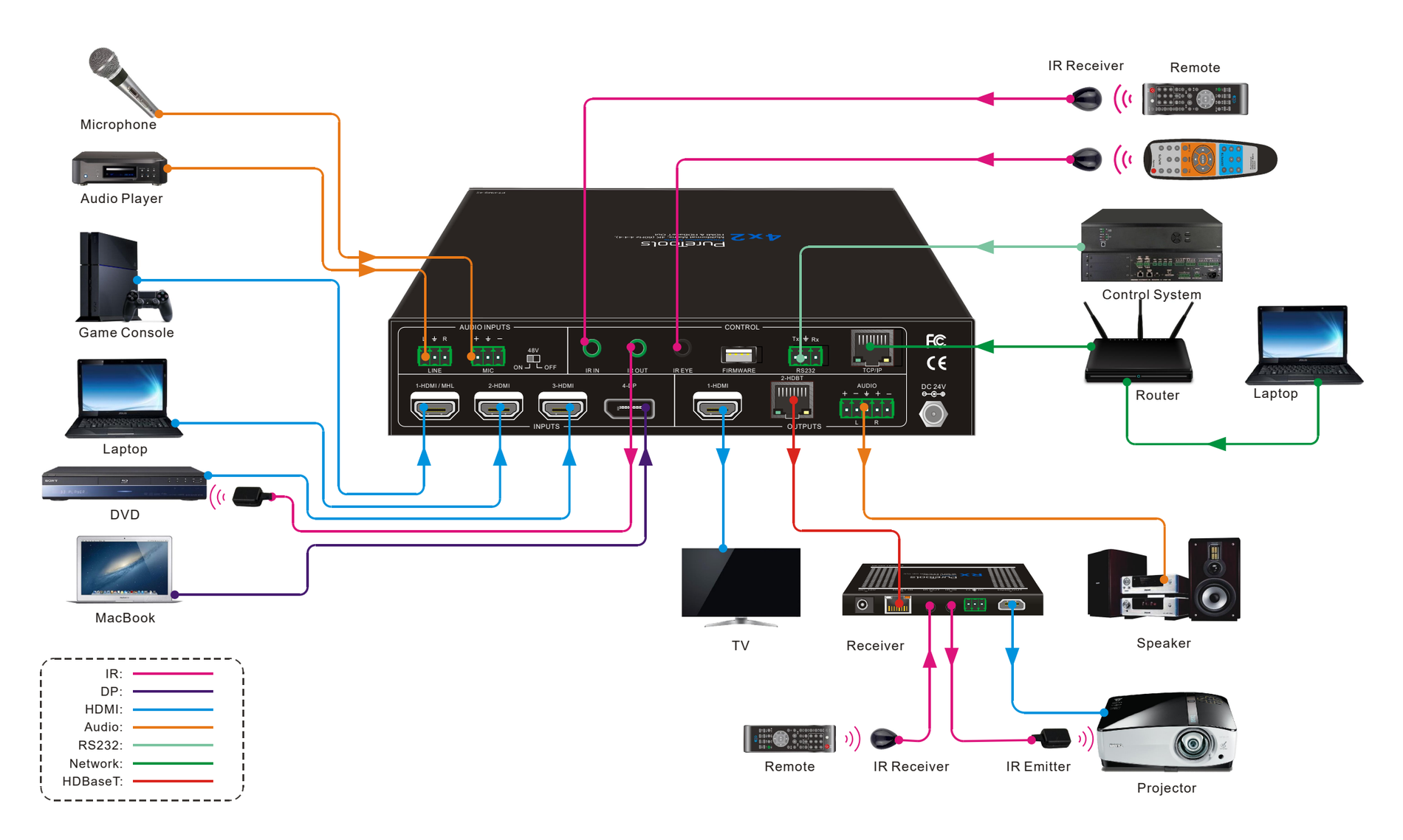
System Diagram
Automatic Switching
Press 1-HDMI or 2-HDBT output button, and then press AUTO button to enable automatic switching. The Auto mode LED will light up.
When in Auto mode, the switcher will switch according to the following rules:
- New input: Upon detecting a new input, the switcher will automatically select the new input.
- Reboot: Once power is restored to the switcher, it will automatically reconnect the input before powered off.
- Source removed: When an active source is removed, the switcher will switch to the first available active input starting at HDMI input 1.
- Press the INPUT button (1-HDMI, 2-HDMI, 3-HDMI or 4-DP) can forcibly change the input source. If the corresponding source device is active, it will be switched as input source. If not, the switcher will switch to the first available active input starting at HDMI input 1.
Sound Volume Control
Press Volume Knob to choose MIC, HDMI OUT or HDBT OUT audio needs to be adjusted, the corresponding LED will turn green and keep on.
- Adjusting the Volume Knob in clockwise direction to increase sound volume.
- Adjusting the Volume Knob in anti-clockwise direction to decrease sound volume.
- Press and hold the Volume Knob at least three seconds to mute the selected audio. Rotate the knob to unmute.
IR Remote Control
Connect the IR EYE port to an IR receiver, the switcher can be controlled by the below IR remote.
1 Enter or exit standby mode.
2 Select input source for HDMI output.
3 Enable/disable automatic switching mode for HDMI output.
4 HDMI output black screen.
5 Select input source for HDBT output.
6 Enable/disable automatic switching mode for HDBT output.
7 HDBT output black screen.
8 LINE audio control: Mute, Volume Down and Volume Up.
9 HDMI output audio control: Mute, Volume Down and Volume Up.
10 HDBT output audio control: Mute, Volume Down and Volume Up.
7. GUI Control
The switcher also be controlled via TCP/IP. The default IP settings are:
IP Address: 192.168.0.178
Subnet Mask: 255.255.250.0
Type 192.168.0.178 in the internet browser, it will enter the below log-in webpage:
Username: admin
Password: admin
Video Switching
Type the user name and password, and then click Login to enter the section for video switching.
- HDMI OUTPUT: Switch the selected input source to HDMI output.
- HDBT OUTPUT: Switch the selected input source to HDBT output.
- Preset: Save the current routing status to preset 1~4.
Audio Control
Input audio control
- Line Volume: Mute, Volume Up or Volume Down.
- MIC Volume: Mute, Volume Up or Volume Down.
- Gain Level: Adjust the gain level for input audio source.
Output audio control
- Mix: Audio mixing output. Step1: Select HDMI De-embedded or HDBT De-embedded audio source for HDBT Output and Audio Output (5-pin) respectively. Note that the HDMI output can not be mixed with other audio, and it only output HDMI De-embedded audio. Step2: Select LINE or MIC, or both of them to mix with the HDMI de-embedded audio or HDBT de-embedded audio. If select MIC or LINE for the HDBT Output, the Audio Output will automatically select the same audio.
- Volume: Volume control bar for output audio. Mute, Volume Up or Volume Down.
- Bypass: Enable or disable Bypass mode. The default is OFF, the audio output format is PCM. When in Bypass mode, the output audio format is the same as the input audio and the output volume cannot be adjusted by the volume control bar.
EDID Management
- Select the compatible built-in EDID for 1-HDMI/MHL, 2-HDMI, 3-HDMI, or 4-DP input source.
- Upload user-defined EDID.
CEC Control
If the input sources and display are supports CEC, they can be controlled by the below control buttons to replace IR remote.
1-HDMI Output Channel
- Source Control: Select the input source which needs to be control, and then press source control button.
- Display Control: Press control button.
2-HDBT Output Channel
RS232 Control
Port Mode
- HDBT Pass Through: Enable RS232 pass-through mode. The RS232 port of the switcher can be used to transfer commands to control other third-party devices.
- Local Control: Disable RS232 pass-through mode. The RS232 port of the switcher is used to connect control device (such as PC) to control the switcher.
Command
- Select Local or HDBT control mode. Local: Send RS232 commands to control the local third-party which is connected to the RS232 port of the PT-PMS-42 switcher. HDBT: Send RS232 commands to control the far-end third-party (such as projector) which is connected to the RS232 port of HDBaseT receiver.
- Select HEX or ASCII format.
- Baud Rate: Supports 2400, 4800, 9600, 19200, 38400, 57600 or 115200.
- Command Ending: NULL, CR, LF or CR+LF can be chosen.
- Command: Type command in this box to control the third-party device.
Network Setting
- Static IP or Dynamic Host Configuration Protocol (DHCP)
- Modify the static IP Address, Subnet Mask, and Gateway.
Password Setting
- Modify the login password.
- Lock or unlock the front panel buttons.
GUI Update
Please visit at http://192.168.0.178:100 for GUI online upgrade.
Type the username and password (the same as the GUI log-in setting, modified password will be available only after rebooting) to login the configuration interface. After that, click Administration in the source menu to get to Upload Firmware as shown below:
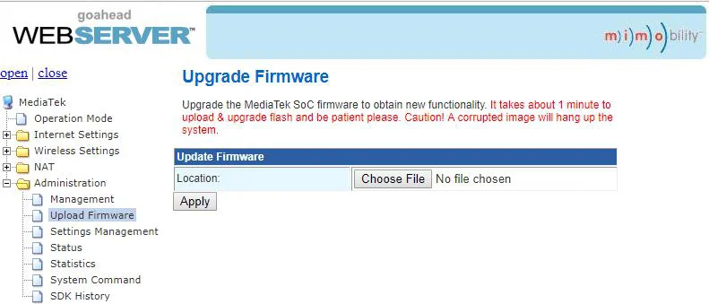
Select the update file and click Apply button, it will start upgrading then.
RS232 Control Software
Connect the RS232 port to control device (such as PC) with RS232 cable. The switcher can be controlled by sending RS232 commands.
Here take the software docklight as an example.
Installation
- Please download the latest Software Version from the link below: https://docklight.de/download/Docklight.zip
- Then follow the installation wizard for installation on Windows 7 and 10.
- After the installation, Docklight can be run for the first time and should look like the below screen shot:
- Registration is not necessary unless you wish to save settings on exit, so unless you wish to register click on "OK" to close the window.
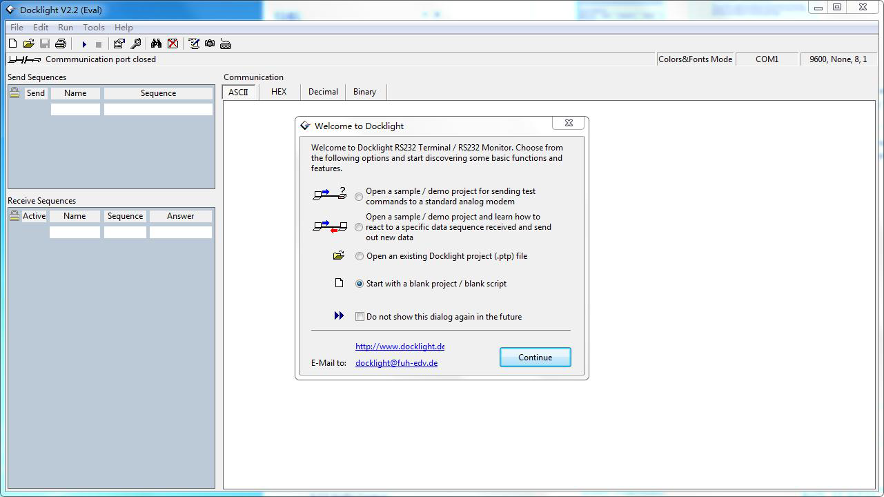
The next pop-up window can also be closed with "Continue". An empty project is enough to send and receive commands easily (The default setting is always “Start with a blank project / blank script “)
Click “Continue” to
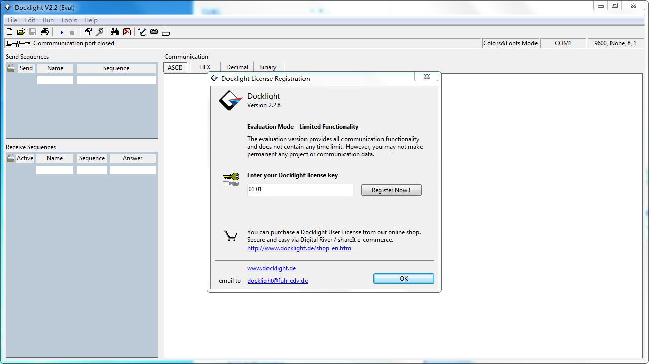
close this window.
Click “OK” to close this window.
Now you are in the main view, where commands are sent and feedback is received.
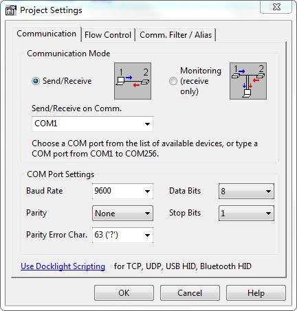
The next step is to select the correct COM port of the PC. To do this, double-click on "COM1" in the corresponding setup window.
In the following window, select the drop-down menu labeled "Send / Receive on Comm Channel", select the appropriate COM port and then click on "OK" at the bottom right corner.
All other settings can be left at default for most applications, but refer to device RS232 settings to be sure.
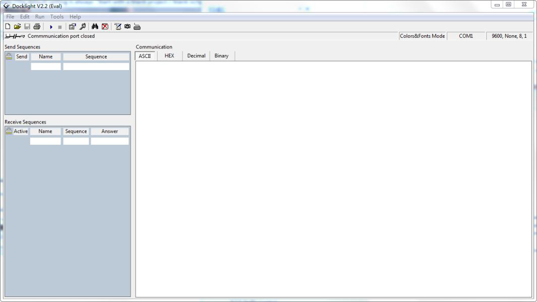
Double click on “COM1” to change to the right COM port.
In order to be able to send commands, open communication with the device by clicking on "Play". (1)
Then the keyboard function must be activated, so that commands can be written in the "communication window". (2)
Finally enter the command, for example "50701%". This is then confirmed by pressing "Enter" to send. Any response from the connected device will appear in red. (3)
Select the right COM port.
Click “Play” to open the communication.
Enable the keyboard type in function.
Command sending area.
Monitoring area, indicates if the command sent works.
1
2
3
RS232 Communication Command
Device Control
| Command | Description | Feedback Example |
|---|---|---|
| PowerON. | Power on system. | Power ON! |
| PowerOFF. | System standby. | Power OFF! |
| /*Name. | Report system name. | 4x2 Matrix Switcher |
| /*Type. | Report system model. | PT-PMS-42 |
| /^Version. | Report firmware version. | V1.0.0 |
| STA. | Report system status. | … … |
| Lock. | Lock front panel buttons. | Front Panel Locked! |
| Unlock. | Unlock front panel buttons. | Front Panel UnLock! |
| GetGuiIP. | Report GUI IP. | GUI_IP:192.168.0.178 |
| SetGuiIP:[xxx.xxx.xxx.xxx]. | Set GUI IP to [xxx.xxx.xxx.xxx]. | |
| SetNoSigTime:[xxx]. | Set the automatic power-off time to xxx. Set the “xxx” as “0” to disable this function. | No Signal Auto StandBy Time Is 0S! |
| Rs232HDBTBypassON. | Enable RS232 pass-through mode. Note: This function can only be disabled by Telnet or GUI. | Rs232 HDBT Bypass ON! |
| Rs232HDBTBypassOFF. | Disable RS232 pass-through mode. Note: The command must be send by Telnet port or GUI RS232 tab. | Rs232 HDBT Bypass OFF! |
| RemoteCtrMcuON. | Allows the switcher to be controlled by the far-end control device which is connected to the RS232 port of HDBaseT receiver. | Remote Control MCU ON! |
| RemoteCtrMcuOFF. | The switcher cannot be controlled by the far-end control device | Remote Control MCU OFF! |
| RST. | Factory reset. | Factory Default! |
Source Switching
| Command | Description | Feedback Example |
|---|---|---|
| HDMI[x]. | Switch input [x] to HDMI output. x=1~4. Example: HDMI4. | HDMI Out Switch To 04! |
| HDBT[x]. | Switch input [x] to HDBT output. x=1~4. Example: HDBT4. | HDBT Out Switch To 04! |
| [x]ALL. | Switch input [x] to HDMI and HDBT outputs. x=1~4. Example: 1ALL. | HDMI Out Switch To 01! HDBT Out Switch To 01! |
| HDBTA. | Automatically switch input source to HDBT output. | HDBT Out Switch Auto Mode! |
| HDBTM. | Manually switch input source to HDBT output. | HDBT Out Switch Manual Mode! |
| HDMIA. | Automatically switch input source to HDMI output. | HDMI Out Switch Auto Mode! |
| HDMIM. | Manually switch input source to HDMI output. | HDMI Out Switch Manual Mode! |
| HDBTBlackON. | Enable HDBT output black screen. | HDBT Out Black ON! |
| HDBTBlackOFF. | Disable HDBT output black screen. | HDBT Out Black OFF! |
| HDMIBlackON. | Enable HDMI output black screen. | HDMI Out Black ON! |
| HDBTBlackOFF. | Disable HDMI output black screen. | HDMI Out Black OFF! |
Audio Control
| Command | Description | Feedback Example |
|---|---|---|
| [x]Gain:[y]. | Set the audio gain of input [x] to [y]. x=1~4, y=0~10. Example: 1Gain:5. | Input 1 Gain Level 5! |
| HDMIABON. | Enable HDMI output audio bypass mode. | HDMI Audio Bypass ON! |
| HDMIABOFF. | Disable HDMI output audio bypass mode. | HDMI Audio Bypass OFF! |
| HDBTABON. | Enable HDBT output audio bypass mode. | HDBT Audio Bypass ON! |
| HDBTABOFF. | Disable HDBT output audio bypass mode. | HDBT Audio Bypass OFF! |
| MicVolume:xx. | Set the MIC volume to xx. | Volume of MIC 80! |
| MicVolume+. | Increase MIC volume. | Volume of MIC 81! |
| MicVolume-. | Decrease MIC volume. | Volume of MIC 79! |
| MicMute. | Mute MIC audio. | Volume of MIC Mute! |
| MicUnMute. | Unmute MIC audio. | Volume of MIC UnMute! |
| LineVolume:xx. | Set the line volume to xx. | Volume of Line 50! |
| LineVolume+. | Increase line volume. | Volume of Line 51! |
| LineVolume-. | Decrease line volume. | Volume of Line 49! |
| LineMute. | Mute line audio. | Volume of Line Mute! |
| LineUnMute. | Unmute line audio. | Volume of Line Unmute! |
| HDMIOutVolume:xx. | Set the HDMI output volume to xx. | Volume of HDMI Out 70! |
| HDMIOutVolume+. | Increase HDMI output volume. | Volume of HDMI Out 71! |
| HDMIOutVolume-. | Decrease HDMI output volume. | Volume of HDMI Out 69! |
| HDMIOutVolumeMute. | Mute HDMI output audio. | Volume of HDMI Out Mute! |
| HDMIOutVolumeUnMute. | Unmute HDMI output audio. | Volume of HDMI Out Unmute! |
| HDBTOutVolume:xx. | Set the HDBT output volume to xx. | Volume of HDBT Out 60! |
| HDBTOutVolume+. | Increase HDBT output volume. | Volume of HDBT Out 61! |
| HDBTOutVolume-. | Decrease HDBT output volume. | Volume of HDBT Out 59! |
| HDBTOutVolumeMute. | Mute HDBT output audio. | Volume of HDBT Out Mute! |
| HDBTOutVolumeUnMute. | Unmute HDBT output audio. | Volume of HDBT Out Unmute! |
Preset Setting
| Command | Description | Feedback Example |
|---|---|---|
| PresetSave[x]. | Store the current switching status to preset [x]. x=1~ 4. Example: PresetSave1. | Preset1 Save Success! |
| PresetRecall[x]. | Recall the preset [x]. x=1~ 4. Example: PresetRecall1. | Preset1 Recall Success! HDMI Out Switch To 04! HDBT Out Switch To 01! |
EDID Management
| Command | Description |
|---|---|
| EDIDSTA[xx]. | Get the EDID status of input [xx]. xx=00 ~ 05. xx Input 00 All inputs 01 1-HDMI/MHL 02 2-HDMI 03 3-HDMI 04 4-DP 1 05 4-DP 2 |
Note: The 4-DP input port supports MST (Multi-Stream Transport). It will automatically output dual path signals when connected to one source device.
- Example: EDIDSTA02.
- Feedback: Input 2 EDID From 02 Internal EDID! Explanation: The input 3 is invoking the EDID 2.
- Example: EDIDSTA03
- Feedback: Input 3 EDID From User Define EDID! Explanation: The input 3 is invoking the user-defined EDID.
| Command | Description |
|---|---|
| EDIDUpgrade[x]. | Upgrade the EDID data of the input port [x]. x=0: All inputs. x=1~4: 1~4 input. x=U: User-defined EDID. When the command applied, system prompts to upload the EDID file (.bin). Operation will be cancelled in 10 seconds. Please disconnect HDBT connection before sending command to ensure the data can be received successfully. |
Please send the EDID file …
EDID Upgrade OK!
| Command | Description |
|---|---|
| EDID/[x]/[y]. | The input [x] invoke built-in EDID [y]. x=0: All inputs. x=1~4: 1~4 input. y EDID 1 720p 2D PCM 2 1080p 2D PCM 3 4K@60Hz 4:2:0 Dolby/DTS 5.1 CH 4 4K@60Hz 4:4:4 HDR 7.1CH 5 User-defined EDID |
- EDID/3/3
| Command | Description |
|---|---|
| EDIDGHDMI. | Get the EDID data from HDMI output. |
| EDIDGHDBT. | Get the EDID data from HDBT output. |
| EDIDM[x]B[y]. | Set the EDID data of output [x] to input [y]. x=1~2, y=1~4. Example: EDIDM1B1. Feedback: Input 1 EDID Upgrade OK By 01 EXT EDID! |
CEC Control
If the input sources and displays are supports CEC, they can be controlled by sending CEC commands to replace IR remote.
- According to the below command to enable CEC control.
| Command | Description | Feedback Example |
|---|---|---|
| CEC_ON. | Enable CEC | CEC ON! |
| CEC_OFF. | Disable CEC | CEC OFF! |
- According to the below command format to send specific command to control input source or display device.
CEC[I/O][port][command].
- The “[I]” represents the input port. The “[O]” represents the output port.
- The “[port]” represents the port number. The input ports are 01~04, and the output ports are 01~02.
- The “[port]” is “FF” for sending command to all input or output ports.
- The “[command]” represents the specific command from the table below.
Control the input source
| Command | Description | Example and Feedback |
|---|---|---|
| CECI[port]00. | Confirm operation (Enter). | CECI0100. CEC_IN_01_SEND_SUCCESS! |
| CECI[port]01. | UP. | CECI0101. CEC_IN_01_SEND_SUCCESS! |
| CECI[port]02. | DOWN. | CECI0102. CEC_IN_01_SEND_SUCCESS! |
| CECI[port]03. | LEFT. | CECI0103. CEC_IN_01_SEND_SUCCESS! |
| CECI[port]04. | RIGHT. | CECI0104. CEC_IN_01_SEND_SUCCESS! |
| CECI[port]0A. | Enter main menu. | CECI010A. CEC_IN_01_SEND_SUCCESS! |
| CECI[port]0D. | Exit menu. | CECI010D. CEC_IN_01_SEND_SUCCESS! |
| CECI[port]41. | Volume up. | CECI0141. CEC_IN_01_SEND_SUCCESS! |
| CECI[port]42. | Volume down. | CECI0142. CEC_IN_01_SEND_SUCCESS! |
| CECI[port]43. | Mute | CECI0143. CEC_IN_01_SEND_SUCCESS! |
| CECI[port]44. | Play. | CECI0144. CEC_IN_01_SEND_SUCCESS! |
| CECI[port]45. | Stop. | CECI0145. CEC_IN_01_SEND_SUCCESS! |
| CECI[port]46. | Pause. | CECI0146. CEC_IN_01_SEND_SUCCESS! |
| CECI[port]48. | Rewind. | CECI0148. CEC_IN_01_SEND_SUCCESS! |
| CECI[port]49. | Fast forward. | CECI0149. CEC_IN_01_SEND_SUCCESS! |
| CECI[port]4B. | Forward. | CECI014B. CEC_IN_01_SEND_SUCCESS! |
| CECI[port]4C. | Backward. | CECI014C. CEC_IN_01_SEND_SUCCESS! |
| CECI[port]6C. | Power off. | CECI016C. CEC_IN_01_SEND_SUCCESS! |
| CECI[port]6D. | Power on. | CECI016D. CEC_IN_01_SEND_SUCCESS! |
Control the output display
| Command | Description | Example and Feedback |
|---|---|---|
| CECO[port]41. | Volume up. | CECO0141. CEC_OUT_01_SEND_SUCCESS! |
| CECO[port]42. | Volume down. | CECO0142. CEC_OUT_01_SEND_SUCCESS! |
| CECO[port]43. | Mute | CECO0143. CEC_OUT_01_SEND_SUCCESS! |
| CECO[port]6C. | Power off. | CECO016C. CEC_OUT_01_SEND_SUCCESS! |
| CECO[port]6D. | Power on. | CECO016D. CEC_OUT_01_SEND_SUCCESS! |
Third-party Device Control
The switcher supports RS232 pass-through control, the third-party device can be controlled by RS232 command, and the command format as shown below:
| Command Function | Command Example |
|---|---|
| /+[X]/[Y]:xxx. | xxx: ASCII characters. Y: Represents the RS232 port.  Y=1: The RS232 port of PT-PMS-42 switcher.  Y=2: The RS232 port of HDBaseT receiver. X: Represents the baud rate of third-party device.  X=1, 2400  X=2, 4800  X=3, 9600  X=4, 19200  X=5, 38400  X=6, 57600  X=7, 115200 / /+3/2:123456. Send the command “123456” to the third-party device. The baud rate is 9600. |
| Command | Description | Example |
|---|---|---|
| CMDON/+[X]:xxx. | Power on the third-party device. | CMDON/+3:455665. |
| CMDOFF/+[X]:xxx. | Power off the third-party device. | CMDOFF/+3:455666. |
Note: When sending HEX command in this box, the “/+[X]/[Y]:” and the end mark “.” must be converted to hexadecimal characters. For example, send the HEX command “F0 01 01 02 0A” to the third-party whose baud rate is 9600. The “/+3/2:” and the point “.” Is converted to “2F 2B 33 2F 32 3A” and “2E”, thus the complete HEX command is “2F 2B 33 2F 32 3A F0 01 01 02 0A 2E”.
Firmware Upgrade
- Prepare the latest upgrade file (.bin) and rename it as “USERAPP.bin” on PC.
- Power off the switcher, and connect the FIRMWARE port of switcher to the PC with USB cable.
- Power on the switcher, and then the PC will automatically detect a U-disk named of “BOOTDISK”.
- Double-click the U-disk, a file named of “READY.TXT” would be showed.
- Directly copy the latest upgrade file (.bin) to the “BOOTDISK” U-disk.
- Reopen the U-disk to check the filename “READY.TXT” whether automatically becomes “SUCCESS.TXT”, if yes, the firmware was updated successfully, otherwise, the firmware updating is fail, the name of upgrade file (.bin) should be confirm again, and then follow the above steps to update again.
- Remove the USB cable after firmware upgrade.
- After firmware upgrade, the switcher should be restored to factory default by sending command.
Panel Drawing
3-HDMI 2-HDMI 1-HDMI / MHL 4-DP 1-HDMI 2-HDBT
L R AUDIO 48V LINE L R OFF MIC IR EYE IR IN IR OUT FIRMWARE RS232 Tx Rx INPUTS OUTPUTS AUDIO INPUTS CONTROL ON DC 24V 220.0mm 44.0mm 172.5mm VOLUME IR 1-HDMI/MHL 1-HDMI 4-DP AUTO 3-HDMI 2-HDMI INPUT OUTPUT 2-HDBT MIC HDBT OUT HDMI OUT MUTE/3s 4x2 Presentation Matrix Multiformat Matrix, 4K (60Hz 4:4:4), HDMI & HDBaseT Out PT-PMS-42 4x2 4K Presentation Switcher 115.0 mm 84.0 mm 16.0 mm HDBaseT Receiver
Troubleshooting & Maintenance
| Problems | Potential Causes | Solutions |
|---|---|---|
| Output image with snowflake. | Bad quality of the connecting cable. | Try another high-quality cable. |
| Fail or loose connection. | Make sure the connection is good. | |
| No output image when switching. | No signal at the input / output end. | Check with oscilloscope or multimeter if there is any signal at the input/ output end. |
| Fail or loose connection. | Make sure the connection is good. | |
| The switcher is broken. | Send it to authorized dealer for repairing. | |
| POWER indicator doesn’t work or no respond to any operation. | Fail connection of power cord. | Make sure the power cord connection is good. |
| EDID management does not work normally. | The HDMI cable is broken at the output end. | Change for another HDMI cable which is in good working condition. |
| Static becomes stronger when connecting the video connectors. | Bad grounding. | Check the grounding and make sure it is connected well. |
| Cannot control the device by control device (e.g. a PC) through RS232 port. | Wrong RS232 communication parameters. | Type in correct RS232 communication parameters. |
| Broken RS232 port. | Send it to authorized dealer for checking. | |
| Cannot control the device by front panel buttons while can control it through RS232 port | The front panel buttons are locked. | Send command /%Unlock; to unlock the front panel buttons. |
Note: If your problem still persists after following the above troubleshooting steps, please find further assistance.
After-Sales Service
If there appear some problems when running the product, please check and deal with the problems referring to this user manual. Any transport costs are borne by the users during the warranty period.
- Product Limited Warranty: The product will be free from defects in materials and workmanship for two years (The purchase invoice shall prevail). Proof of purchase in the form of a bill of sale or receipted invoice which is evidence that the unit is within the Warranty period must be presented to obtain warranty service.
- What the warranty does not cover (servicing available for a fee): Warranty expiration. Factory applied serial number has been altered or removed from the product. Damage, deterioration or malfunction caused by: Normal wear and tear. Use of supplies or parts not meeting our specifications. No certificate or invoice as the proof of warranty. The product model shown on the warranty card does not match with the model of the product for repairing or had been altered. Damage caused by force majeure. Servicing not authorized by distributor. Any other causes which does not relate to a product defect. Delivery, installation or labor charges for installation or setup of the product.
- Technical Support: For any questions or problems, contact your distributor or reseller and tell them the respective product name and version, the detailed failure situation as well as the formation of the cases.
Asking for Assistance
Technical Support:
Phone: +49 5971 800299 - 0
Fax: +49 5971 800299 - 99
Technical Support Hours:
8:30 AM to 5:00 PM Monday thru Thursday
8:30 AM to 4:00 PM Friday
Write to:
PureLink GmbH
Von-Liebig-Straße 10
D - 48432 Rheine
www.purelink.de
info@purelink.de
Legal & Compliance
Product identification
Model: PT-PMS-42 – manual version 1.0
Trademarks and disclaimer
Product model and logo are trademarks. All other company and product names mentioned are trademarks of their respective owners. All rights reserved. No part of this publication may be copied or reproduced without prior written permission. We reserve the right to make changes to the device, packaging or manual and accept no liability for misprints.
EU conformity
PureLink hereby declares that this product PureTools PT-PMS-42complies with Directives 1907/2006/EU und 2011/65/EU. PureLink GmbH hereby declares that this product PureTools PT-PMS-42 complies with Directives 2014/30/EU and 2014/35/EU.
| Directive / Regulation |
|---|
| 1907/2006/EU |
| 2011/65/EU |
| 2014/30/EU |
| 2014/35/EU |
The full text of the EU Declaration of Conformity is available at: http://www.purelink.de/ce/4251364718216_CE.pdf
FCC
Statement This equipment generates, uses and can radiate radio frequency energy and, if not installed and used in accordance with the instructions, may cause harmful interference to radio communications. It has been tested and found to comply with the limits for a Class B digital device, pursuant to part 15 of the FCC Rules. These limits are designed to provide reasonable protection against harmful interference in a commercial installation.
Disposal of electrical and electronic equipment
WEEE reg. no.: DE 93847290
The crossed-out wheelie bin symbol on the product, packaging or in this manual means that electrical and electronic equipment must not be disposed of with household waste at the end of its life. Hand in old devices free of charge at a public collection point or return them to a distributor obliged to take them back. Remove batteries and lamps that can be removed without destroying the device before handing it in, and delete any personal data stored on the device. Details are regulated by national law. By returning old devices you help protect the environment.
Batteries
Batteries must not be disposed of with household waste. Return used batteries free of charge to collection points or retailers.
Packaging
Dispose of packaging separately by material (paper/cardboard, plastics) via the local collection systems. Keep packaging material away from children – risk of suffocation. Packaging register LUCID: DE5958616449295.