
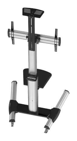
Instructions of safety and warnings
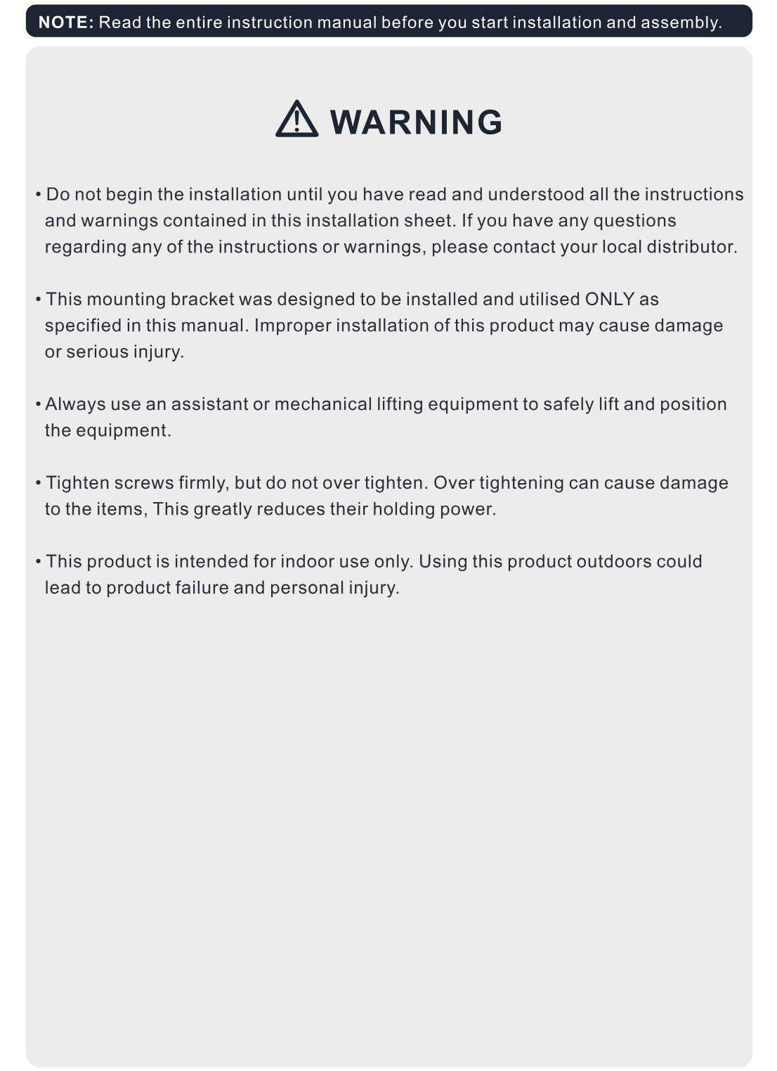
IMPORTANT: Please read thoroughly and retain for future reference. Do not attempt to assemble or use this product if you are not familiar with and capable of doing so.
- This product must be installed according to the provided instructions. Improper installation may result in personal injury or property damage.
- Ensure the cart is suitable for your TV and can safely support the specified weight and environment.
- Maximum load capacity must not be exceeded.
- Tighten all safety and operating devices securely before use.
- Regularly inspect all parts to ensure the cart operates correctly and safely.
- Do not use if parts are worn or damaged.
- Do not allow children to climb or hang on the cart or accessories.
- Use only on a flat and stable surface. Lock castors after moving.
- Do not move the cart when equipment is installed.
- Keep packaging materials away from children.
- Failure to follow safety instructions may result in injury, product damage, or property damage.
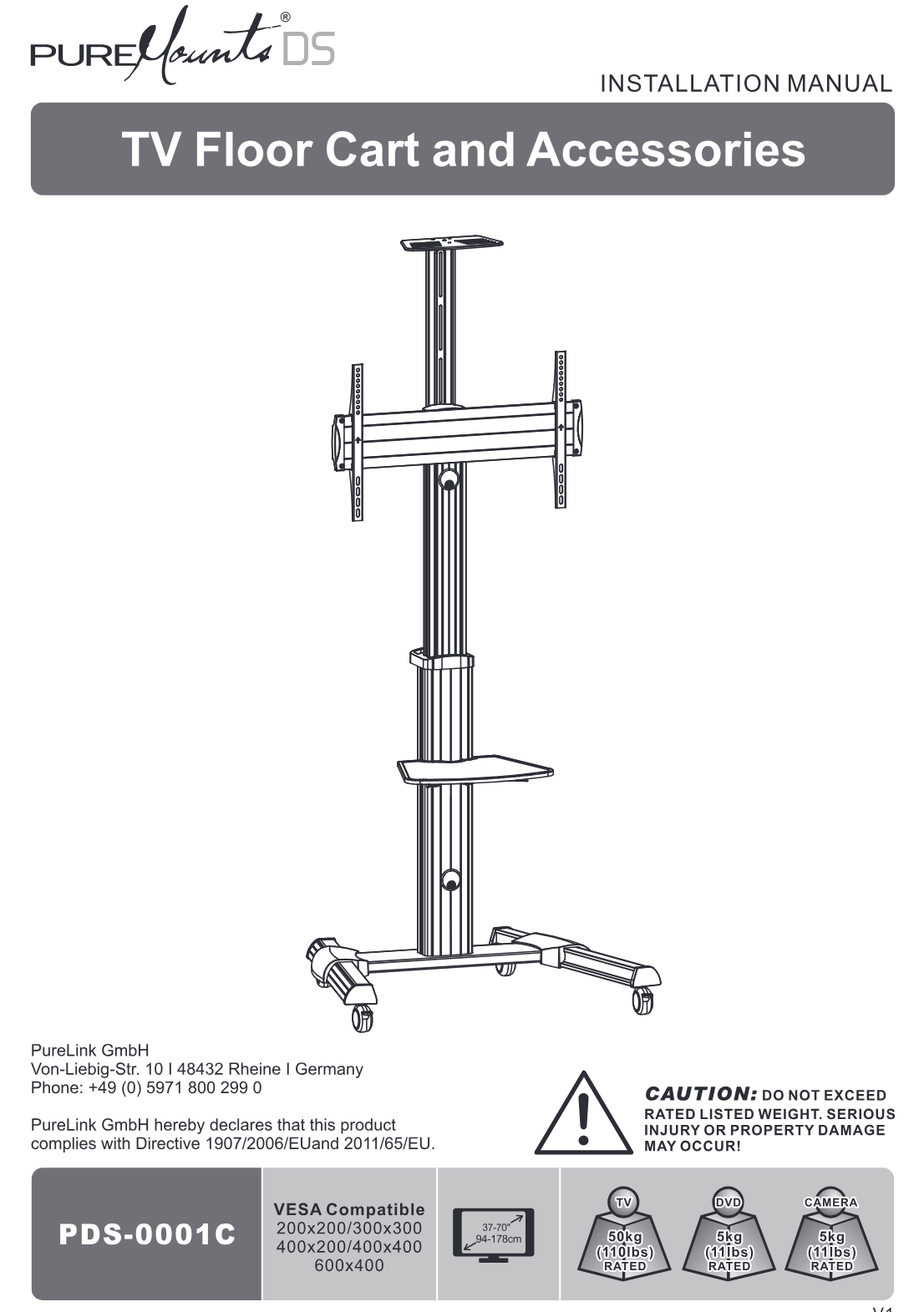
PureLink GmbH
Von-Liebig-Str. 10 | 48432 Rheine | Germany
Phone: +49 (0) 5971 800 299 0
PureLink GmbH hereby declares that this product complies with Directive 1907/2006/EU and 2011/65/EU.
Caution: DO NOT EXCEED RATED LISTED WEIGHT. SERIOUS INJURY OR PROPERTY DAMAGE MAY OCCUR!
| VESA Compatible | 5kg (11lbs) RATED | CAMERA |
|---|---|---|
| 200x200/300x300 | 5kg (11lbs) RATED | CAMERA |
| 400x200/400x400 | 5kg (11lbs) RATED | CAMERA |
| 600x400 | 5kg (11lbs) RATED |
Assembling the Base
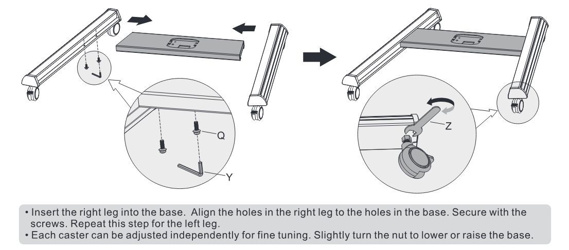
Insert the right leg into the base. Align the holes in the right leg to the holes in the base. Secure with the screws. Repeat this step for the left leg.
Each caster can be adjusted independently for fine tuning. Slightly turn the nut to lower or raise the base.
Attaching the Column to the Base
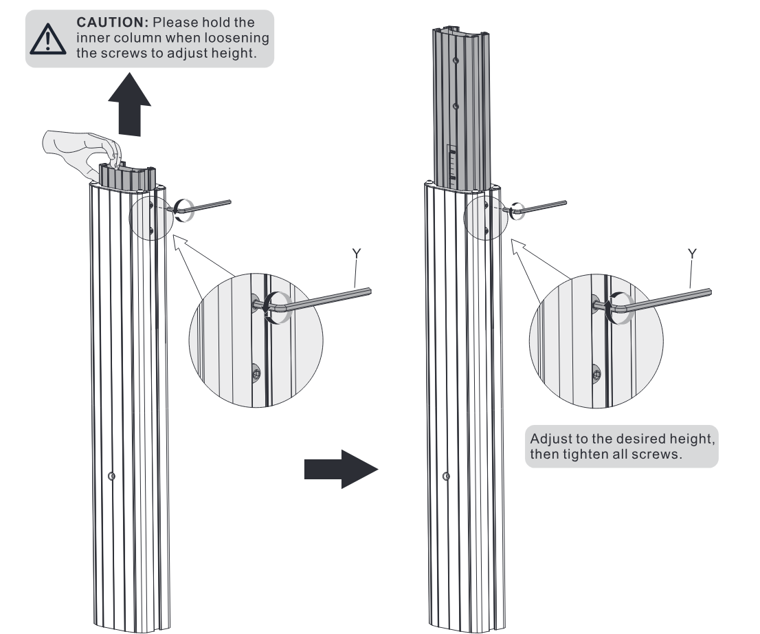
Caution: Please hold the inner column when loosening the screws to adjust height.
Adjust to the desired height, then tighten all screws.
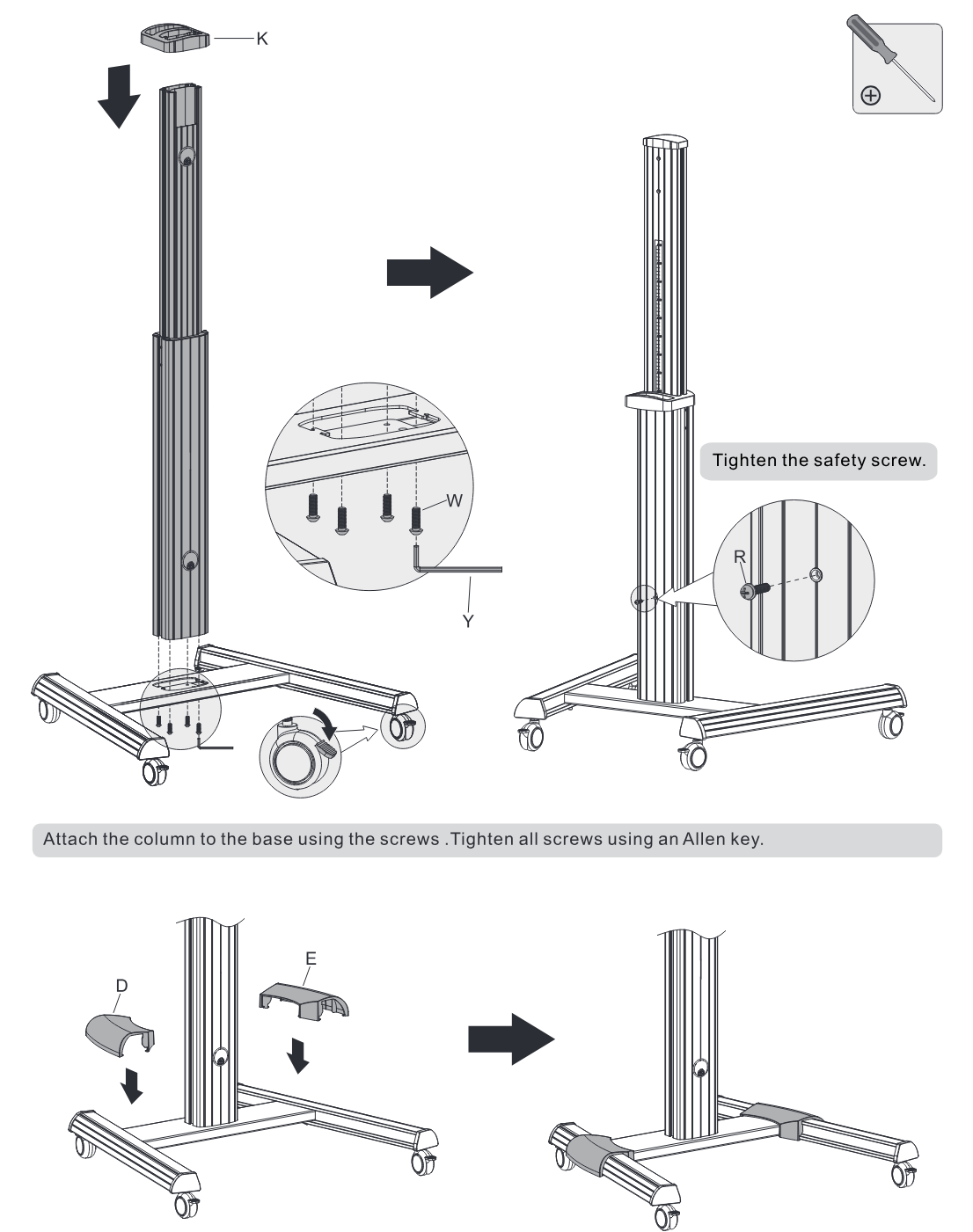
Attach the column to the base using the screws. Tighten all screws using an Allen key.
Tighten the safety screw.
Installing the Support Plate
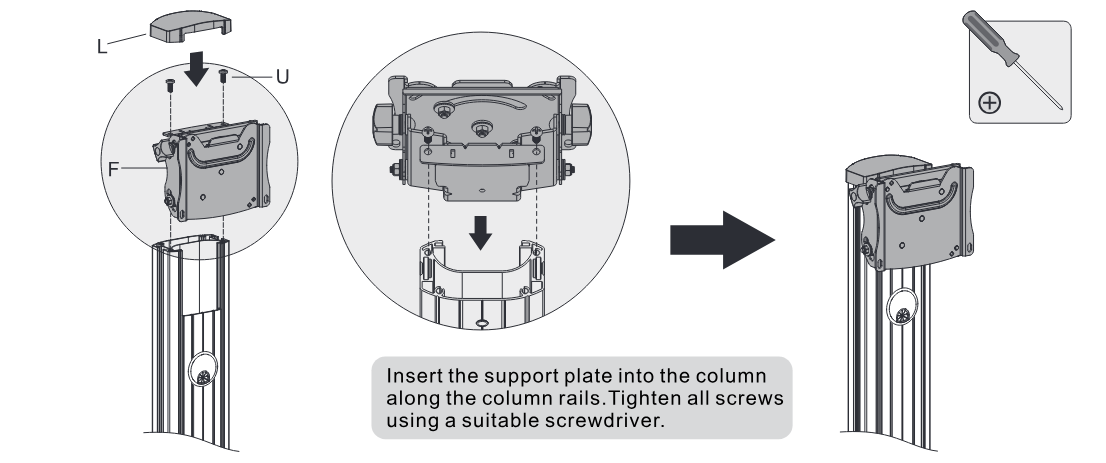
Insert the support plate into the column along the column rails. Tighten all screws using a suitable screwdriver.
Installing the Adapter Brackets
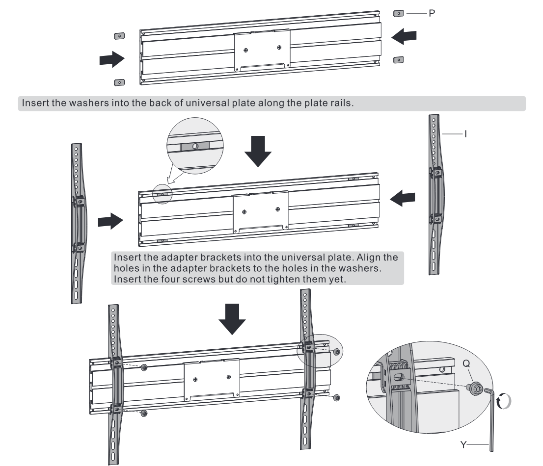
Insert the washers into the back of universal plate along the plate rails.
Insert the adapter brackets into the universal plate. Align the holes in the adapter brackets to the holes in the washers. Insert the four screws but do not tighten them yet.
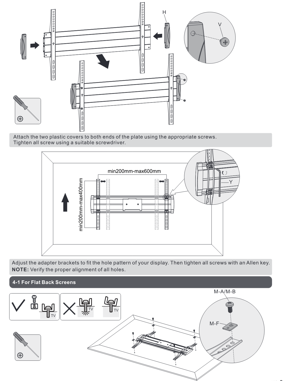
Attach the two plastic covers to both ends of the plate using the appropriate screws. Tighten all screw using a suitable screwdriver.
Adjust the adapter brackets to fit the hole pattern of your display. Then tighten all screws with an Allen key.
Note: Verify the proper alignment of all holes.
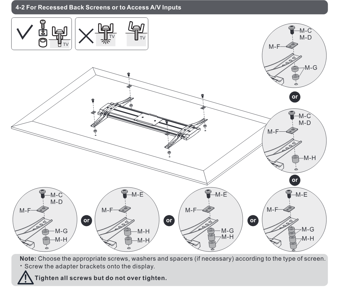
4-1 For Flat Back Screens
Hooking the Display onto the Support Plate
4-2 For Recessed Back Screens or to Access A/V Inputs
Note: Choose the appropriate screws, washers and spacers (if necessary) according to the type of screen.
Screw the adapter brackets onto the display.
Tighten all screws but do not over tighten.
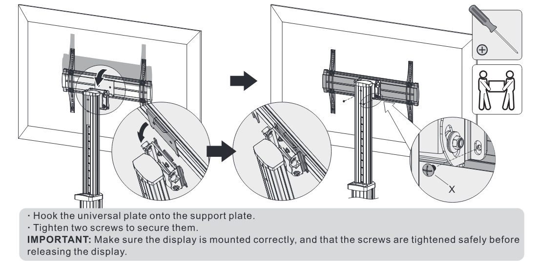
Hook the universal plate onto the support plate.
Tighten two screws to secure them.
IMPORTANT: Make sure the display is mounted correctly, and that the screws are tightened safely before releasing the display.
Installing the DVD Shelf
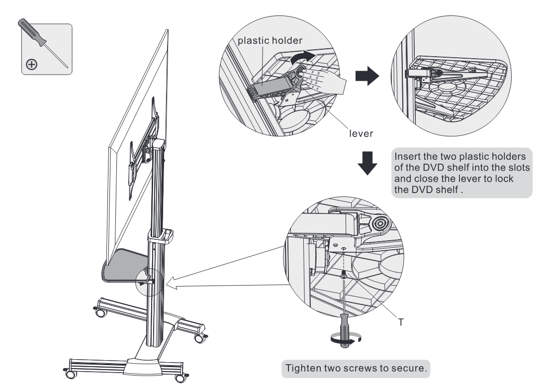
Insert the two plastic holders of the DVD shelf into the slots and close the lever to lock the DVD shelf.
Tighten two screws to secure.
Cable Management
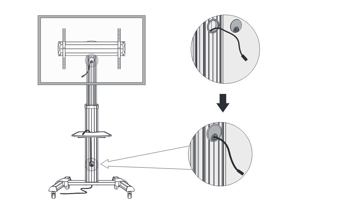
Installing the Camera Shelf
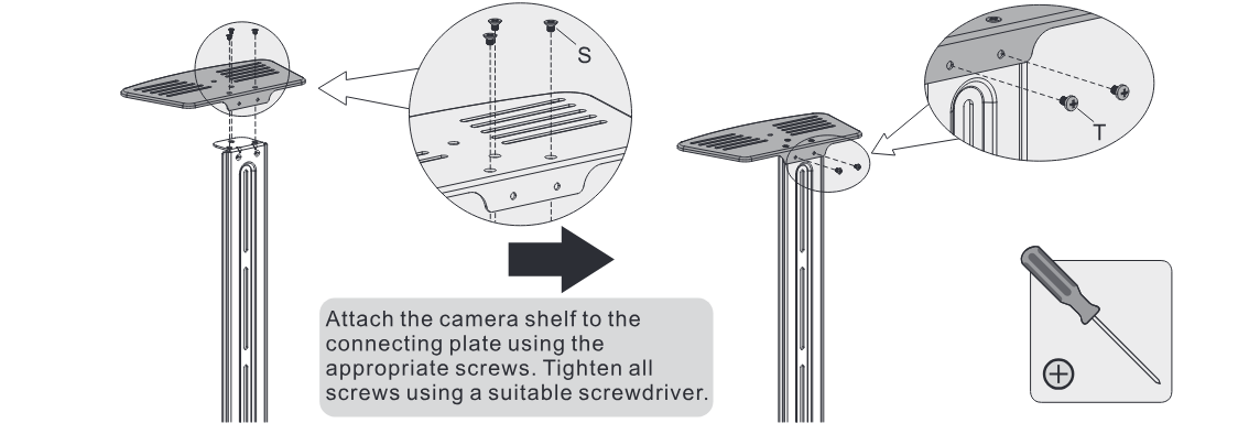
Attach the camera shelf to the connecting plate using the appropriate screws. Tighten all screws using a suitable screwdriver.
Installing the Connecting Plate
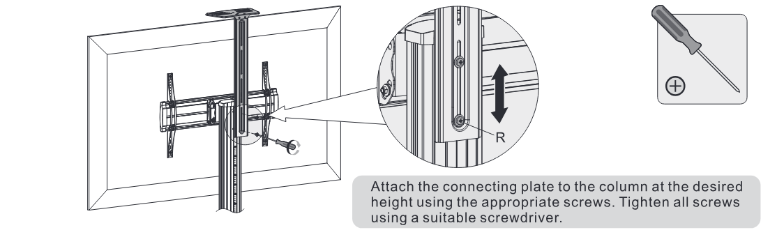
Attach the connecting plate to the column at the desired height using the appropriate screws. Tighten all screws using a suitable screwdriver.
Display Orientation
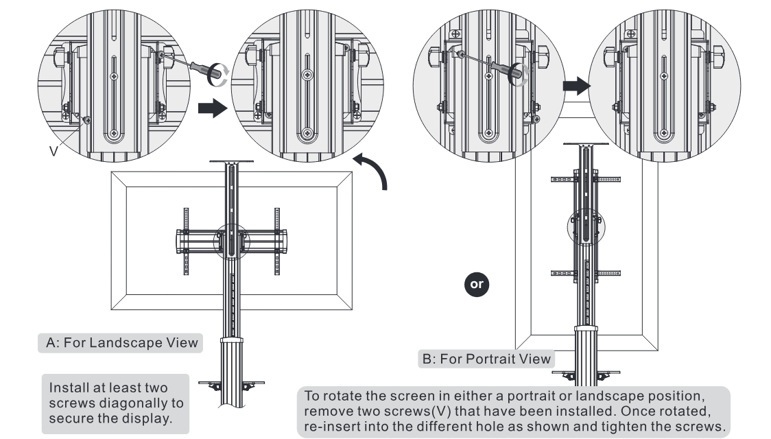
A: For Landscape View
Install at least two screws diagonally to secure the display.
or
B: For Portrait View
To rotate the screen in either a portrait or landscape position, remove two screws (V) that have been installed. Once rotated, re-insert into the different hole as shown and tighten the screws.
Adjustment
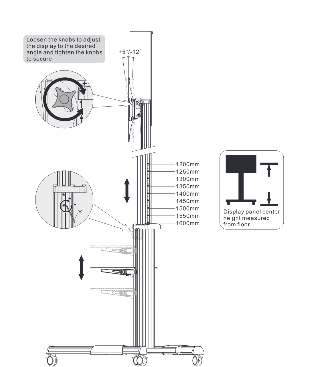
Loosen the knobs to adjust the display to the desired angle and tighten the knobs to secure.
1200mm | 1250mm | 1300mm | 1350mm | 1400mm | 1450mm | 1500mm | 1550mm | 1600mm
Display panel center height measured from floor.
Maintenance
- Check that the bracket is secure and safe to use at regular intervals (at least every three months).
Please contact your distributor if you have any questions.
Legal & Compliance
Product identification
Model: PDS-0001C – manual version 1.0
Warranty and liability
The manufacturer grants the full statutory warranty on all new devices. As the manufacturer has no influence on installation, the warranty only applies to the product itself. If you detect a fault or damage, please contact your dealer and provide your sales slip or invoice as proof of purchase.
The manufacturer is not liable for damage to persons or property caused by improper installation, operation or maintenance not described in this manual. Do not alter or modify the product or its accessories. Any use other than described in this manual is not permitted and voids warranty and guarantee.
Trademarks and disclaimer
Product model and logo are trademarks. All other company and product names mentioned are trademarks of their respective owners. All rights reserved. No part of this publication may be copied or reproduced without prior written permission. We reserve the right to make changes to the device, packaging or manual and accept no liability for misprints.
Packaging
Dispose of packaging separately by material (paper/cardboard, plastics) via the local collection systems. Keep packaging material away from children – risk of suffocation. Packaging register LUCID: DE5958616449295.