
Active
PT-MA-HD44HDBT
4x4 4K 18Gbps HDMI HDBaseT Matrix with Audio Matrix and ARC
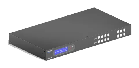
The 4x4 4K 18Gbps HDMI HDBaseT Matrix with Audio Matrix and ARC is a 1U rack-mount matrix switch featuring 4 HDBaseT outputs with mirrored HDMI outputs, supporting 18Gbps bandwidth and 4K resolution at 60Hz with HDR10 …
ManualControl (TCP/IP)FAQSpecificationsCE declaration ↗Available control interfaces. Expand an active type to see the full command table.
No matching commands.
RS-232 Commands38 commandsActive
Source: manual, chapter RS232 Communication Commands, page 16
| Command | Description | Response | |
|---|---|---|---|
| PowerON. | Power on the system. | Power ON! | |
| PowerOFF. | Power off the system. | Power OFF! | |
| /*Name. | Report product name. | MUH44T-H2 | |
| /*Type. | Report product model. | HDBaseT Matrix | |
| /^Version. | Report software version. | V1.0.0 CPLD:V1.0.0 VideoDriverVersion:V1.0.0 | |
| RST. | Reset to factory default. | Factory Default! | |
| Lock. | Lock front panel buttons. | Front Panel Locked! | |
| Unlock. | Unlock front panel buttons. | Front Panel UnLock! | |
| GetGuiIP. | Report the GUI IP. | GUI_IP:192.168.0.178! | |
| SetGuiIP:xxx.xxx.xxx.xxx. | Set the GUI IP to xxx.xxx.xxx.xxx. | SetGuiIP:192.168.0.176. SetGuiIP:192.168.0.176! | |
| Baudrate115200. | Set the serial baud rate of matrix switcher to 115200. | Set Local RS232 Baudrate Is 115200! | |
| Baudrate57600. | Set the serial baud rate of matrix switcher to 57600. | Set Local RS232 Baudrate Is 57600! | |
| Baudrate38400. | Set the serial baud rate of matrix switcher to 38400. | Set Local RS232 Baudrate Is 38400! | |
| Baudrate19200. | Set the serial baud rate of matrix switcher to 19200. | Set Local RS232 Baudrate Is 19200! | |
| Baudrate9600. | Set the serial baud rate of matrix switcher to 9600. | Set Local RS232 Baudrate Is 9600! | |
| PHDBTON. | Enable PoC of HDBT outputs for powering HDBaseT receivers. | HDBT Power ON! | |
| PHDBTOFF. | Disable PoC of HDBT outputs. | HDBT Power OFF! | |
| STA_PHDBT. | Report the PoC status of HDBT outputs. | HDBT Power ON! | |
| DS[XX]ON. | Enable the video resolution auto-downscaling function of HDMI output [XX]. [XX]=00~04. The “[XX]=00” represents all HDMI outputs. | DS00ON. HDMI OUT 01 Down Scale ON! HDMI OUT 02 Down Scale ON! HDMI OUT 03 Down Scale ON! HDMI OUT 04 Down Scale ON! | |
| DS[XX]OFF. | Disable the video resolution auto-downscaling function of HDMI output [XX]. [XX]=00~04. The “[XX]=00” represents all HDMI outputs. | DS00OFF. HDMI OUT 01 Down Scale OFF! HDMI OUT 02 Down Scale OFF! HDMI OUT 03 Down Scale OFF! HDMI OUT 04 Down Scale OFF! | |
| STA_DS. | Report the auto-downscaling function of HDMI outputs. | HDMI OUT 01 Down Scale OFF! HDMI OUT 02 Down Scale OFF! HDMI OUT 03 Down Scale OFF! HDMI OUT 04 Down Scale OFF! | |
| RS232RCM[XX]ON. | Enable the RS232 remote-control mode for HDBT output [XX] that the matrix switcher can be controlled from remote PC. [XX]=00~04. The “[XX]=00” represents all HDBT outputs. | RS232RCM00ON. RS232 Remote 01 Control MCU ON! RS232 Remote 02 Control MCU ON! RS232 Remote 03 Control MCU ON! RS232 Remote 04 Control MCU ON! | |
| RS232RCM[XX]OFF. | Disable the RS232 remote-control mode for HDBT output [XX] that the matrix switcher cannot be controlled from remote PC. [XX]=00~04. The “[XX]=00” represents all HDBT outputs. | RS232RCM00OFF. RS232 Remote 01 Control MCU OFF! RS232 Remote 02 Control MCU OFF! RS232 Remote 03 Control MCU OFF! RS232 Remote 04 Control MCU OFF! | |
| STA_RS232RCM. | Report the RS232 remote-control mode status. | RS232 Remote 01 Control MCU OFF! RS232 Remote 02 Control MCU OFF! RS232 Remote 03 Control MCU OFF! RS232 Remote 04 Control MCU OFF! | |
| IRRCM[XX]ON. | Enable the IR remote-control mode for HDBT output [XX] that the matrix switcher can be controlled by the IR remote at the far-end HDBaseT receivers’ position. [XX]=00~04. The “[XX]=00” represents all HDBT outputs. | IRRCM00ON. IR Remote 01 Control MCU ON! IR Remote 02 Control MCU ON! IR Remote 03 Control MCU ON! IR Remote 04 Control MCU ON! | |
| IRRCM[XX]OFF. | Disable the IR remote-control mode for HDBT output [XX] that the matrix switcher cannot be controlled by the IR remote at the far-end HDBaseT receivers’ position. [XX]=00~04. The “[XX]=00” represents all HDBT outputs. | IRRCM00OFF. IR Remote 01 Control MCU OFF! IR Remote 02 Control MCU OFF! IR Remote 03 Control MCU OFF! IR Remote 04 Control MCU OFF! | |
| STA_IRRCM. | Report the IR remote-control mode status. | IR Remote 01 Control MCU ON! IR Remote 02 Control MCU ON! IR Remote 03 Control MCU ON! IR Remote 04 Control MCU ON! | |
| @OUT[XX]. | Turn on output [XX]. [XX]=00~08. The “[XX]=00” represents all outputs. [XX]=01~04, represents HDBT output 1~4. [XX]=05~08, represents HDMI output 1~4. | @OUT00. Turn ON Output 01! Turn ON Output 02! Turn ON Output 03! Turn ON Output 04! Turn ON Output 05! Turn ON Output 06! Turn ON Output 07! Turn ON Output 08! | |
| $OUT[XX]. | Turn off output [XX]. [XX]=00~08. The “[XX]=00” represents all outputs. [XX]=01~04, represents HDBT output 1~4. [XX]=05~08, represents HDMI output 1~4. | $OUT00. Turn OFF Output 01! Turn OFF Output 02! Turn OFF Output 03! Turn OFF Output 04! Turn OFF Output 05! Turn OFF Output 06! Turn OFF Output 07! Turn OFF Output 08! | |
| STA_POUT. | Report the on/off status of all outputs. | Turn ON Output 01! Turn ON Output 02! Turn ON Output 03! Turn ON Output 04! Turn ON Output 05! Turn ON Output 06! Turn ON Output 07! Turn ON Output 08! | |
| STA. | Report all system status. | GUI Or RS232 Query Status: HDBaseT Matrix MUH44T-H2 V1.0.0 Power ON! HDBT Power ON! Front Panel UnLock! Local RS232 Baudrate Is 9600! GUI_IP:192.168.0.178! Output 01 Switch To In 01! | |
| STA_IN. | Report the connection status of all HDMI input ports. | IN 1 2 3 4 LINK N N N Y | |
| STA_OUT. | Report the connection status of all HDMI and HDBT outputs. | OUT 1 2 3 4 5 6 7 8 LINK N N N Y N N N N | |
| IRFVON. | Enable the IR switching to follow the video switching. | IR Follow Video ON! | |
| IRFVOFF. | Disable the IR switching to follow the video switching. | IR Follow Video OFF! | |
| OUT[XX]:[YY]. | Switch video input [YY] to video output [XX]. [XX]=00~04, [YY]=01~04. The “[XX]=00” represents all outputs. | OUT01:04. Output 01 Switch To In 04! | |
| STA_VIDEO. | Report the input channel for all outputs. | Output 01 Switch To In 01! Output 02 Switch To In 02! Output 03 Switch To In 03! Output 04 Switch To In 04! | |
| IR[XX]:[YY]. | Switch far-end IR IN [YY] to local IR OUT [XX]. [XX]=01~04, [YY]=00~04. The “[YY]=00” represents all far-end IR IN ports. | IR01:03. Local 01 IR Out Switch To Remote 03 IR IN! |
RS-232 Commands31 commandsActive
Source: manual, chapter Command Description, page 61
| Command | Description | Example | Response | |
|---|---|---|---|---|
| STA_IR. | Report IR switching status. | IR Follow Video ON! Local 01 IR Out Switch To Remote 01 IR IN! Local 02 IR Out Switch To Remote 02 IR IN! Local 03 IR Out Switch To Remote 03 IR IN! Local 04 IR Out Switch To Remote 04 IR IN! | ||
| PresetSave[XX]. | Store the current switching status to present [XX]. XX=01~09. | PresetSave01. | Preset 01 Save Success! Preset 01 Sta: Out 01 In 01! Out 02 In 02! Out 03 In 03! Out 04 In 04! | |
| SPDIF[XX]:[YY]. | Select audio source [YY] for SPDIF audio output [XX]. [XX]=00~04, The “[XX]=00” represents all SPDIF audio outputs. [YY]=01~12. | SPDIF01:04. | ||
| STA_SPDIF. | Report SPDIF audio status. | SPDIF Out 01 Switch To Video In 01! SPDIF Out 02 Switch To Video In 02! SPDIF Out 03 Switch To Video In 03! SPDIF Out 04 Switch To Video In 04! | ||
| AVOLUME[XX]:[YY]. | Set the volume of analog L+R audio output [XX] to [YY]. [XX]=00~04, The “00” represents all L+R audio outputs. | AVOLUME00:V+. AVOLUME00:V-. AVOLUME01:MU. AVOLUME01:UM. AVOLUME01:05. AVOLUME01:100. | Analog Out 01 Volume 61! Analog Out 02 Volume 61! Analog Out 03 Volume 61! Analog Out 04 Volume 61! Analog Out 01 Volume Mute! Analog Out 02 Volume Mute! Analog Out 03 Volume Mute! Analog Out 04 Volume Mute! Analog Out 01 Volume UnMute! Analog Out 02 Volume UnMute! Analog Out 03 Volume UnMute! Analog Out 04 Volume UnMute! | |
| ANALOG[XX]:[YY]. | Select audio source [YY] for analog L+R audio output [XX]. [XX]=00~04, The “[XX]=00” represents all L+R audio outputs. [YY]=01~08. | ANALOG01:04. | ||
| STA_ANALOG. | Report analog L+R audio status. | Analog Out 01 Switch To Video In 01! Analog Out 01 Volume UnMute! Analog Out 01 Volume 60! Analog Out 02 Switch To Video In 02! Analog Out 02 Volume UnMute! Analog Out 02 Volume 60! Analog Out 03 Switch To Video In 03! Analog Out 03 Volume UnMute! Analog Out 03 Volume 60! Analog Out 04 Switch To Video In 04! Analog Out 04 Volume UnMute! Analog Out 04 Volume 60! | ||
| EDIDMInit. | Reset factory default EDID to all input ports. | All Input EDID Set Default! | ||
| EDIDUpgrade[XX]. | Upgrade the EDID data of the input port [XX]. [XX]=00~04, U. [XX]=00, represents all inputs. [XX]=01~04, represents HDMI input 1~4. [XX]=U, upload a user-defined EDID. The EDID can be saved for invoking at any time. When the command applied, system prompts to upload the EDID file (.bin). Operation will be cancelled in 10 seconds. Please disconnect HDBT connection before sending command to ensure the data can be received successfully. | EDIDUpgrade01. EDIDUpgradeU. | 256 9600bps Input XX/User Define EDID Upgrade OK By RS232 Or GUI! | |
| EDID/[XX]/[YY]. | The input [XX] recall the embedded EDID [YY]. [XX]=00~04. The “00” represents all inputs. [YY]=01~07. | EDID/03/01. | ||
| EDIDGOUT[XX]. | Report the EDID data from output [XX]. [XX]=01~08. [XX]=01~04, represents HDBT output 1~4. [XX]=05~08, represents HDMI output 1~4. | EDIDGOUT04. | ||
| EDIDM[XX]B[YY]. | Copy the EDID data of output [XX] to input [YY]. [XX]=01~08, [YY]=00~04. [XX]=01~04, represents HDBT output 1~4. [XX]=05~08, represents HDMI output 1~4. [YY]=00, represents all inputs. [YY]=01~04, represents HDMI input 1~4. | EDIDM04B01. | ||
| EDIDSTA[XX]. | Report the EDID status of input [XX]. [XX]=00~04. [XX]=00, represents all inputs. [XX]=01~04, represents HDMI input 1~4. | EDIDSTA00. | ||
| /+[X]/[YY]:xxx. | Send the ASCII command “xxx” to control the far-end third-party device. • xxx: ASCII string. • The “[X]=1~7” represents the baud rate of third-party device. [X]=1, the baud rate is 2400 [X]=2, the baud rate is 4800 [X]=3, the baud rate is 9600 [X]=4, the baud rate is 19200 [X]=5, the baud rate is 38400 [X]=6, the baud rate is 57600 [X]=7, the baud rate is 115200 • The “[YY]=00” represents all HDBT outputs. • The “[YY]=01~04” represents the HDBT output 1~4. | /+3/01:123456. | ||
| CMDON/+[X]/[YY]:xxx. | When power on the matrix switcher, automatically send ASCII command “xxx” to power on far-end third-party device. • xxx: ASCII string. • The “[X]=1~7” represents the baud rate of third-party device. [X]=1, the baud rate is 2400 [X]=2, the baud rate is 4800 [X]=3, the baud rate is 9600 [X]=4, the baud rate is 19200 [X]=5, the baud rate is 38400 [X]=6, the baud rate is 57600 [X]=7, the baud rate is 115200 • The “[YY]=00” represents all HDBT outputs. • The “[YY]=01~04” represents the HDBT output 1~4. | CMDON/+3/01:123456. | ||
| CMDOFF/+[X]/[YY]:xxx. | When power off the matrix switcher, automatically send ASCII command “xxx” to power off far-end third-party device. • xxx: ASCII string. • The “[X]=1~7” represents the baud rate of third-party device. [X]=1, the baud rate is 2400 [X]=2, the baud rate is 4800 [X]=3, the baud rate is 9600 [X]=4, the baud rate is 19200 [X]=5, the baud rate is 38400 [X]=6, the baud rate is 57600 [X]=7, the baud rate is 115200 • The “[YY]=00” represents all HDBT outputs. • The “[YY]=01~04” represents the HDBT output 1~4. | CMDOFF/+3/01:123456. | ||
| CECI[AA][BB][CC]00. | Confirm operation (Enter). | CECI02044400 | CECI02044400 CEC Input 02 Send Success! | |
| CECI[AA][BB][CC]01. | UP direction. | CECI01044401. | CECI01044401. CEC Input 01 Send Success! | |
| CECI[AA][BB][CC]02. | DOWN direction. | CECI01044402. | CECI01044402. CEC Input 01 Send Success! | |
| CECI[AA][BB][CC]03. | LEFT direction. | CECI03044403. | CECI03044403. CEC Input 03 Send Success! | |
| CECI[AA][BB][CC]04. | RIGHT direction. | CECI03044404. | CECI03044404. CEC Input 03 Send Success! | |
| CECI[AA][BB][CC]09. | Back to submenu. | CECI03044409. | CECI03044409. CEC Input 03 Send Success! | |
| CECI[AA][BB][CC]0A. | Enter main menu. | CECI0304440A. | CECI0304440A. CEC Input 03 Send Success! | |
| CECI[AA][BB][CC]0D. | Exit menu. | CECI0204440D. | CECI0204440D. CEC Input 02 Send Success! | |
| CECI[AA][BB][CC]6D. | Power on. | CECI0204446D. | CECI0204446D. CEC Input 02 Send Success! | |
| CECI[AA][BB][CC]6C. | Power off. | CECI0204446C. | CECI0204446C. CEC Input 02 Send Success! | |
| CECO[AA][BB][CC]41. | Volume up. | CECO05404441. | CECO05404441. CEC Output 05 Send Success! | |
| CECO[AA][BB][CC]42. | Volume down. | CECO05404442. | CECO05404442. CEC Output 05 Send Success! | |
| CECO[AA][BB][CC]43. | Mute | CECO05404443. | CECO05404443. CEC Output 05 Send Success! | |
| CECO[AA][BB]04. | Power on. | CECO038004. | CECO038004. CEC Output 03 Send Success! | |
| CECO[AA][BB]36. | Power off. | CECO038036. | CECO038036. CEC Output 03 Send Success! |