
Discontinued
PT-PMS-62
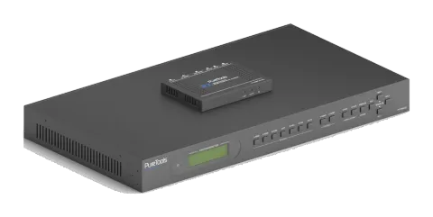
6x2 4K Multiformat Presentation Matrix with Scaler Set
The PT-PMS-62 is a professional scaling presentation matrix featuring two fully independent outputs, including a 4K HDMI port and an HDBaseT port that can transmit up to 70m at 1080p or 40m at 4K, with the included …
ManualControl (TCP/IP)FAQSpecificationsCEAvailable control interfaces. Expand an active type to see the full command table.
No matching commands.
RS-232 Commands99 commandsActive
Source: manual, chapter RS232 Control, page 41
| Command | Description | Example | Response | |
|---|---|---|---|---|
| PWON. | Power on system. | PWON | ||
| PWOFF. | Power off system. Turn off HDBaseT power supply. | PWOFF | ||
| STANDBY. | System standby. Press any button to awake. | STANDBY | ||
| /*Type; | Report system model. | PT-PMS-62S | ||
| /^Version; | Report firmware version. | V1.0.0 | ||
| /%Lock; | Lock front panel buttons. | System Locked | ||
| /%Unlock; | Unlock front panel buttons. | System Unlock! | ||
| %9964. | Report IP address. | IP:192.168.0.178 | ||
| USBUpdata:[x]. | Upgrade the 3458 IC of the port [x]. X Port 1~6 Input port 7~8 Output port | |||
| %9961. | Report the system locking status. | System UnLock/Lock! | ||
| %9962. | Report the system power status. | PWON/PWOFF | ||
| %0911. | Reset to factory default. Note: The switcher must be restarted after factory reset to ensure signal output. | |||
| Demo. | Switch to demo testing mode, switch AV 1>1, 1>2 and so on. | Demo Mode: AV:01->01 AV:01->02 AV:02->01 AV:02->02 AV:03->01 AV:03->02 AV:04->01 AV:04->02 AV:05->01 AV:05->02 AV:06->01 AV:06->02 Normal Mod | ||
| Undo. | Cancel the current operation and return to the previous switching status. | Undo Ok! | ||
| [x]All. | Switch input [x] to HDMI and HDBT outputs. x=1~6. Example: 4ALL. | 4 To All | ||
| All#. | Switch all input signal to the corresponding output channel. 1->1, 2->2 | All Through. | ||
| All$. | Turn off all channels. | All Closed. | ||
| [x]#. | Switch input [x] to output [x]. x=1~2. | 1 Through | ||
| [x]$. | Turn off output [x]. x=1~2. | 1 Closed. | ||
| [x]@. | Turn on output [x]. x=1~2. | 01 Open. | ||
| All@. | Turn on all outputs. | All Open | ||
| [x]V[y]. | Switch input [x] to output [y]. x=1~8, y=1~2. | AV: 1-> 1 | ||
| %9975. | Report the source switching status. | Out 1 2 In 4 4 | ||
| Status[x]. | Report the output [x] status. x=1~2 | AV: 5-> 1 | ||
| Status. | Report the input channel on output channel one by one. | AV:01->01 AV:01->02 | ||
| Save[y]. | Store the current switching status to preset [y]. y=0~9. | Save To F0 | ||
| Recall[y]. | Recall the preset [y]. y=0~9. | Recall From F0 | ||
| Clear[y]. | Clear the preset [y]. | Clear F0 | ||
| Embedded:[x]. | Select external balanced audio (L+R) for input [x]. x=1~2. | HDMI1 Embedded | ||
| UnEmbedded:[x]. | Select internal audio for input [x]. x=1~2. | HDMI1 UnEmbedded | ||
| MIXOUT:[x]. | The output [x] audio is mixed with MIX audio. | HDMI1 OUT MIX | ||
| UnMIXOUT:[x]. | The output [x] audio is not mixed with MIX audio. | HDMI1 OUT UnMIX | ||
| SetHDMIVol:xx. | Set the HDMI output audio volume to xx. xx=0~60. | Volume of HDMI: 30. | ||
| HDMIVolume+. | Increase the HDMI output audio volume. | Volume of HDMI: 31. | ||
| HDMIVolume-. | Decrease the HDMI output audio volume. | Volume of HDMI: 29. | ||
| HDMIMute. | Mute the HDMI output audio. | HDMI Mute. | ||
| HDMIUnmute. | Unmute the HDMI output audio. | HDMI Unmute. | ||
| SetHDBTVol:xx. | Set the HDBT output audio volume to xx. xx=0~60. | Volume of HDBT: 30. | ||
| HDBTVolume+. | Increase the HDBT output audio volume. | Volume of HDBT: 31. | ||
| HDBTVolume-. | Decrease the HDBT output audio volume. | Volume of HDBT: 29. | ||
| HDBTMute. | Mute the HDBT output audio. | HDBT Mute. | ||
| HDBTUnmute. | Unmute the HDBT output audio. | HDBT Unmute. | ||
| SetMIXVol:xx. | Set the MIX input audio volume to xx. xx=0~60. | Volume of MIX: 30. | ||
| MIXVolume+. | Increase the MIX input audio volume. | Volume of MIX: 31. | ||
| MIXVolume-. | Decrease the MIX input audio volume. | Volume of MIX: 29. | ||
| MIXMute. | Mute the MIX input audio. | MIX Mute. | ||
| MIXUnmute. | Unmute the MIX input audio. | MIX Unmute. | ||
| %9941. | Report the audio status. | HDBT Unmute. HDMI Mute. MIX Mute. | ||
| %9942. | Report the audio volume. | Volume of HDBT: 9. Volume of HDMI: 30. Volume of MIX: 6. | ||
| %9943. | Report the external audio status. | HDMI1 Unembedded HDMI2 Embedded | ||
| VRES/X:Y. | Set the output resolution of port [X] to [Y]. 1) X=7/8: X Output Port 7 HDMI 8 HDBT 2) Y=1~10: Y Resolution 1 4K@60Hz 2 4K@30Hz 3 1920X1200@60Hz 4 1080P@60Hz 5 1080P@50Hz 6 1600x1200@60Hz 7 1360x768@60Hz 8 1024x768@60Hz 9 720P@60Hz 10 720P@50Hz | Outport HDMI:720p@50Hz Outport HDBT:720p@50Hz | ||
| EDID/[x]/[y]. | The input [x] invoke built-in EDID [y]. x=1~3, 5. y EDID 1 1080P@60Hz 2 4K@30Hz 4:4:4 3 4K@60Hz 4:4:4 | |||
| EDID Upgrade[x]. | Upgrade the EDID data of the input port [x]. x=1~3, 5. When the command applied, system prompts to upload the EDID file (.bin). Operation will be cancelled in 10 seconds. Please disconnect HDBT connection before sending command to ensure the data can be received successfully. | |||
| EDIDM[x]B[y]. | Set the EDID data of output [x] to input [y]. x=1~2, y=1~3, 5. | Example: EDIDM1B1. Feedback: Input 1 EDID Upgrade OK By 01 EXT EDID! | ||
| EDIDMInit. | Reset factory default EDID to all input ports. | All input EDID Set Default 1080P! | ||
| %9945. | Report the EDID data of all ports. | Inport 1 : Edid_2 Inport 2 : Edid_4 Inport 3 : Edid_1 Inport 4 : Edid_3 Inport 6 : Edid_3 Outport 1 : Edid_3 Outport 2 : Edid_3 | ||
| Relay ON[X]. | Turn on relay [X], X=1~2. | Relay 1 ON | ||
| Relay OFF[X]. | Turn off relay [X], X=1~2. | Relay 1 OFF | ||
| Relay AutomationCtl:[X],[Y]. | Set the auto stop time of relay [X] to Y seconds. X=1~2, Y=0~20. | Relay 1 Turn On, delay 0.0 seconds turn off | ||
| ToggleRelay[X]. | Toggle relay [X], X=1~2. | |||
| SetVGAPhase:XX. | Set the phase position to XX. XX=0~100. | |||
| SetVGABrightness: XX. | Set the brightness to XX. XX=0~100. | SetVGABrightness: 070 | ||
| SetVGAContrast: XX. | Set the contrast to XX. XX=0~100. | SetVGAContrast: 050 | ||
| SetVGAColor: XX. | Set the color to XX. XX=0~100. | SetVGAColor: 020 | ||
| SetVGAAutoSync:X. | X=0, Disable Auto-Sync mode. X=1, Enable Auto-Sync mode. | SetVGAAutoSync: AutoSync OFF/ON | ||
| SetVGASharpness:XX. | Set the sharpness to XX. XX=0~100. | SetVGASharpness: 050 | ||
| SetVGAColorTemp:X. | Auto-adjust the color temperature to X. X=0~3 (Normal/Cool/Warm) | SetVGAColorTemp: COLORTEMP MEDIUM SetVGAColorTemp: COLORTEMP COOL SetVGAColorTemp: COLORTEMP USER | SetVGAColorTemp: COLORTEMP WARM | |
| SetVGAAspetRatio:X. | Set the aspect ratio to X. X=0~2 (16:9/4:3/auto) | SetVGAAspetRatio:AspetRatio 4X3 SetVGAAspetRatio:AspetRatio Auto | SetVGAAspetRatio:AspetRatio 16X9 | |
| SetVGAPicMode:X. | Set the image mode to X. X=0~3. (dynamic/standard/mild/user) | SetVGAPicMode: PICTURE NORMAL MODE SetVGAPicMode: PICTURE VIVID MODE SetVGAPicMode: PICTURE USER MODE | SetVGAPicMode: PICTURE SOFT MODE | |
| Baud rate 2400. | Set the RS232 baud rate of switcher to 2400. | Set Local RS232 baud rate is 2400! | ||
| Baud rate 4800. | Set the RS232 baud rate of switcher to 4800. | Set Local RS232 baud rate is 4800! | ||
| Baud rate 9600. | Set the RS232 baud rate of switcher to 9600. | Set Local RS232 baud rate is 9600! | ||
| Baud rate 19200. | Set the RS232 baud rate of switcher to 19200. | Set Local RS232 baud rate is 19200! | ||
| Baud rate 38400. | Set the RS232 baud rate of switcher to 38400. | Set Local RS232 baud rate is 38400! | ||
| Baud rate 57600. | Set the RS232 baud rate of switcher to 57600. | Set Local RS232 baud rate is 57600! | ||
| Baud rate 115200. | Set the RS232 baud rate of switcher to 115200. | Set Local RS232 baud rate is 115200! | ||
| CECON. | Enable CEC | CEC Turn ON! | ||
| CECOFF. | Disable CEC | CEC Turn OFF! | ||
| CECI[port]00. | Confirm operation (Enter). | CECI0100. [CEC]: blue ray OK. | ||
| CECI[port]01. | UP. | CECI0101. [CEC]: blue ray up. | ||
| CECI[port]02. | DOWN. | CECI0102. [CEC]: blue ray down. | ||
| CECI[port]03. | LEFT. | CECI0103. [CEC]: blue ray left. | ||
| CECI[port]05. | RIGHT. | CECI0105. [CEC]: blue ray right. | ||
| CECI[port]09. | Back to submenu. | CECI0109. [CEC]: blue ray menu. | ||
| CECI[port]0D. | Exit. | CECI010D. [CEC]: blue ray Exit. | ||
| CECI[port]41. | Volume up. | CECI0141. [CEC]: Source VOL + | ||
| CECI[port]42. | Volume down. | CECI0142. [CEC]: Source VOL - | ||
| CECI[port]44. | Play. | CECI0144. [CEC]: blue ray play. | ||
| CECI[port]45. | Stop. | CECI0145. [CEC]: blue ray stop. | ||
| CECI[port]46. | Pause. | CECI0146. [CEC]: blue ray pause. | ||
| CECI[port]48. | Rewind | CECI0148. [CEC]: blue ray backward. | ||
| CECI[port]49. | Fast forward. | CECI0149. [CEC]: blue ray forward. | ||
| CECI[port]4B. | Forward. | CECI014B. [CEC]: blue ray skid forward. | ||
| CECI[port]4C. | Backward. | CECI014C. [CEC]: blue ray skid backward. | ||
| CECI[port]6C. | Power off. | CECI016C. [CEC]: Source Power off. | ||
| CECI[port]6D. | Power on. | CECI016D. [CEC]: Source Power on. | ||
| CECO[port]34. | Input channel selection. | CECO0634. [CEC]: TV input select | ||
| CECO[port]41. | Volume up. | CECO0641. [CEC]: TV VOL + | ||
| CECO[port]42. | Volume down. |
RS232 Commands12 commandsActive
Source: manual, chapter RS232 Control, page 51
| Command | Description | Example | Response | |
|---|---|---|---|---|
| CECI[port]6C. | Power off. | CECI016C. [CEC]: Source Power off. | ||
| CECI[port]6D. | Power on. | CECI016D. [CEC]: Source Power on. | ||
| CECO[port]34. | Input channel selection. | CECO0634. [CEC]: TV input select | ||
| CECO[port]41. | Volume up. | CECO0641. [CEC]: TV VOL + | ||
| CECO[port]42. | Volume down. | CECO0642. [CEC]: TV VOL - | ||
| CECO[port]43. | Mute | CECO0643. [CEC]: TV VOL Mute | ||
| CECO[port]36. | Power off. | CECO0636. [CEC]: TV Power off | ||
| CECO[port]04. | Power on. | CECO0604. [CEC]: TV Power on | ||
| UARTPassThrough:Y. | RS232 mode selection: Y=0, Local Control: The RS232 port of the switcher is used to connect control device (e.g. PC) to control the switcher. Y=1, HDBT Receiver Pass Through: Establish RS232 pass-through communication between the switcher and HDBaseT receiver (e.g.PT-HDBT-200-RX). The RS232 port of the switcher can be used to transfer commands to control the third-party device which is connected to the HDBaseT receiver. | |||
| /+[Y]/[X]:******. | xxx: ASCII characters. Y: Represents the RS232 port. 1) Y=1: The RS232 port of switcher. 2) Y=2: The RS232 port of HDBaseT receiver. 3) Y=3: The RS232 port of HDBaseT transmitter. X: Represents the baud rate of third-party device. 1) X=1, 2400 2) X=2, 4800 3) X=3, 9600 4) X=4, 19200 5) X=5, 38400 6) X=6, 57600 7) X=7, 115200 | /+3/3:123456. Send the command “123456” to the third-party device. The baud rate is 9600. | ||
| /#[X]/[B]:******. | xxxxxx: HEX characters. X: Represents the RS232 port. X RS232 Port 1 The RS232 port on the matrix switcher. 2 The RS232 port on the far-end HDBaseT receiver. B: Represents the baud rate of third-party device. B Baud Rate 1 2400 2 4800 3 9600 4 19200 5 38400 6 57600 7 115200 | /#3/3:01 02 03 Send the HEX command “123456” to the third-party device whose baud rate is 9600. | ||
| /+[Y]/[B]:******. | xxxxxx : Feedback command (ASCII characters). Y : Represents the RS232 port. 1) Y=A: When power on system, receive the feedback command from the RS232 port of switcher. 2) Y=B: When power on system, receive the feedback command from the RS232 port of HDBaseT receiver. 3) Y=a: When power off system, receive the feedback command from the RS232 port of switcher. 4) Y=b: When power off system, receive the feedback command from the RS232 port of HDBaseT receiver. B : Represents the baud rate of third-party device. | /+A/3: Play ON 123. When power on system, receive the feedback command “Play ON 123.” from the RS232 port of switcher. |