
Discontinued
PT-PSW-61E
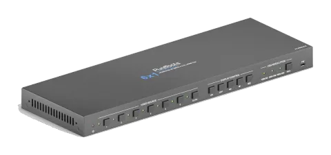
6x1 4K 18Gbps Multiformat Presentation Switcher with Scaler
The 6x1 4K 18Gbps Multiformat Presentation Switcher with Scaler features six switchable input signals including HDMI, MHL, DisplayPort, USB-C, and VGA+Audio, with automatic signal switching to a single HDMI output. It …
ManualControl (TCP/IP)FAQSpecificationsDatasheetFirmwareCE declaration ↗Available control interfaces. Expand an active type to see the full command table.
No matching commands.
RS-232 Commands1 commandsActive
ConnectionBaud Rate: Supports 2400, 4800, 9600, 19200, 38400, 57600 or 115200.
Command Ending: NULL, CR, LF or CR+LF can be chosen.↓ CSV
Source: manual, chapter RS232 Tab, page 24
| Command | Description | Response | |
|---|---|---|---|
| Type the command in this box to control the third-party device which is connected to the RS232 port of the switcher. | Control the third-party device connected to the RS232 port of the switcher. |
RS232 Commands46 commandsActive
Source: manual, chapter RS232 Command, page 31
| Command | Description | Example | Response | |
|---|---|---|---|---|
| POWON. | Power on system. | POWER ON! | ||
| POWOFF. | System standby. | POWER OFF! | ||
| LOCK. | Lock front panel buttons. | FRONT PANEL LOCKED! | ||
| UNLOCK. | Unlock front panel buttons. | FRONT PANEL UNLOCK! | ||
| GETGUIIP. | Report GUI IP. | GUI_IP:192.168.0.178 | ||
| SETGUIIP:[xxx.xxx.xxx.xxx]. | Set GUI IP to [xxx.xxx.xxx.xxx]. Example: SETGUIIP:192.168.0.178. | SETGUIIP:192.168.0.178! | ||
| STA. | Report system status. | GUI/RS232 QUERY STATUS! PT-PSW-61E VERSION V1.0.0 POWER ON! FRONT PANEL UNLOCK! HDMI OUT SWITCH TO AUTO MODE! HDMI OUT SWITCH TO 2! DIP0000! | ||
| RST. | Factory reset. | FACTORY DEFAULT! PT-PSW-61E VERSION V1.0.0 POWER ON! FRONT PANEL UNLOCK! HDMI OUT SWITCH TO AUTO MODE! HDMI OUT SWITCH TO 1! DIP0000! DIP EDID0000! SPDIF OUT ON! IIS OUT ON! | ||
| HELP. | Get the command list. | RS232/GUI COMMANDS LIST: 1 - POWON 2 - POWOFF 3 - RST 4 – UNLOCK … | ||
| HDMI1. | Switch to HDMI input 1. | HDMI OUT SWITCH TO 1! | ||
| HDMI2. | Switch to HDMI input 2. | HDMI OUT SWITCH TO 2! | ||
| HDMI3. | Switch to HDMI input 3. | HDMI OUT SWITCH TO 3! | ||
| HDMI4. | Switch to HDMI input 4. | HDMI OUT SWITCH TO 4! | ||
| HDMI5. | Switch to HDMI input 5. | HDMI OUT SWITCH TO 5! | ||
| HDMI6. | Switch to HDMI input 6. | HDMI OUT SWITCH TO 6! | ||
| HDMIA. | Enable auto switching mode. | HDMI OUT SWITCH TO AUTO MODE! | ||
| HDMIM. | Enable manual switching mode. | HDMI OUT SWITCH TO MANUAL MODE! | ||
| VGARES1. | Set the VGA output resolution to 1024x768@60Hz. | SET RESOLUTION OF VGA OUTPUT TO 1024x768@60Hz! | ||
| VGARES2. | Set the VGA output resolution to 1280x720@50Hz. | SET RESOLUTION OF VGA OUTPUT TO 1280x720@50Hz! | ||
| VGARES3. | Set the VGA output resolution to 1280x720@60Hz. | SET RESOLUTION OF VGA OUTPUT TO 1280x720@60Hz! | ||
| VGARES4. | Set the VGA output resolution to 1360x768@60Hz. | SET RESOLUTION OF VGA OUTPUT TO 1360x768@60Hz! | ||
| VGARES5. | Set the VGA output resolution to 1600x1200@60Hz. | SET RESOLUTION OF VGA OUTPUT TO 1600x1200@60Hz! | ||
| VGARES6. | Set the VGA output resolution to 1920x1080@50Hz. | SET RESOLUTION OF VGA OUTPUT TO 1920x1080@50Hz! | ||
| VGARES7. | Set the VGA output resolution to 1920x1080@60Hz. | SET RESOLUTION OF VGA OUTPUT TO 1920x1080@60Hz! | ||
| VGARES8. | Set the VGA output resolution to 1920x1200@60Hz. | SET RESOLUTION OF VGA OUTPUT TO 1920x1200@60Hz! | ||
| VGAAUTO. | Auto adjust the VGA output image. | VGA AUTO ADJUST! | ||
| VGAUPGR. | Upgrade the firmware Of VGA input port chip | UPGRADING FIRMWARE OF VGA CHIP! | ||
| EDIDR[xxxx]. | Read the preset EDID. [xxxx] represents the 4-pin DIP switch status. | EDID_0001! … | ||
| EDIDUSE[xxxx]. | Invoke the preset EDID. [xxxx] represents the 4-pin DIP switch status. | EDIDUSE0001! EDID_RS232&GUI_MODE! EDID0001! | ||
| EDIDW[xxxx]. | User-define EDID. xxxx = 1011, 1100, 1101 or 1110. Operation: Step 1: Prepare the EDID file (.bin). Step 2: Set the 4-pin DIP switch to “1111” status. Step 3: Send the command “EDIDW1101.”, and the feedback is “PLEASE SEND THE EDID FILE!”. Step 4: Send the EDID file (.bin). If successfully upload, the feedback is: “RECEIVED THE FILE, LENGTH=134! EDID1101 UPDATE SUCCESSFULLY!” | |||
| IISON. | Turn on the stereo analog L/R audio output. | IIS OUT ON! | ||
| IISOFF. | Turn off the stereo analog L/R audio output. | IIS OUT OFF! | ||
| SPDIFON. | Turn on the Toslink digital audio output. | SPDIF OUT ON! | ||
| SPDIFOFF. | Turn off the Toslink digital audio output. | SPDIF OUT OFF! | ||
| TVON. | Power on the display. | CEC TV POWER ON! | ||
| TVOFF. | Power off the display. | CEC TV POWER OFF! | ||
| TVVOL+. | Increase the display audio. | CEC TV VOLUME INCREASE! | ||
| TVVOL-. | Decrease the display audio. | CEC TV VOLUME DECREASE! | ||
| TVMUTE. | Mute/unmute the display. | CEC TV VOLUME MUTE/UNMUTE! | ||
| CECxx . | Send CEC command “yy yy yy” to control the source device or the display device. The “xx” represents the port number. xx Port 00 1-HDMI/MHL IN 01 2-HDMI/MHL IN 02 3-HDMI IN 03 4-USB-C IN 04 5-DP IN 05 HDMI OUT The “ ” represents the specific control command of source device or display device. | CEC00 . Send CEC command “40:44:41” to control the source device which is connected to the 1-HDMI/MHL IN port. | ||
| /+[B]:xxx. | Send the ASCII command “xxx” to the third-party whose baud rate is as defined. The “B” represents the baud rate of third-party device. B=1, the baud rate is 2400 B=2, the baud rate is 4800 B=3, the baud rate is 9600 B=4, the baud rate is 19200 B=5, the baud rate is 38400 B=6, the baud rate is 57600 B=7, the baud rate is 115200 | /+3:abc123 | ||
| /-[B]:xx xx xx. | Send the HEX command “xx xx xx xx” to the third-party whose baud rate is as defined. The “B” represents the baud rate of third-party device. B=1, the baud rate is 2400 B=2, the baud rate is 4800 B=3, the baud rate is 9600 B=4, the baud rate is 19200 B=5, the baud rate is 38400 B=6, the baud rate is 57600 B=7, the baud rate is 115200 | /-3:1A 2A 3A 4A | ||
| CMDON/+[B]:xxx. | Send ASCII command “xxx” to power on the third-party device. | CMDON/+3:abc123 | ||
| CMDON/-[B]:xx xx xx. | Send HEX command “xx xx xx” to power on the third-party device. | CMDON/-3:1A 2A 3A 4A | ||
| CMDOFF/+[B]:xxx. | Send ASCII command “xxx” to power off the third-party device. | CMDOFF/+3:abc123 | ||
| CMDOFF/-[B]:xxx. | Send HEX command “xx xx xx” to power off the third-party device. | CMDOFF/-3:1A 2A 3A 4A |