
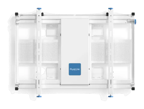
INSTALLATION SAFETY INSTRUCTIONS
This mount is intended for use with flat screens that do not exceed the maximum weight indicated of 135Kgs (300lbs.). Exceeding this weight limit will result in instability, causing possible injury.
Do not attempt to install this product until all instructions and warnings have been read and properly understood.
Please keep these instructions for future reference.
Please check carefully to make sure there are no missing or defective parts. Defective parts must never be used.
PureLink GmbH, its distributors and dealers are not liable or responsible for damage or injury caused by improper installation, improper use or failure to observe these safety instructions. In such cases, all guarantees will expire.
General
PureLink GmbH recommends that only a professional AV installer or other suitably qualified persons, install this product. Great care must always be taken during installation as AV equipment is fragile, heavy and easily damaged.
If you do not fully understand the instructions or are not sure how to install this product safely, then please consult a professional for advice and/or to install this product for you. Failure to mount this product correctly may cause serious injury, death or both during installation and at any time thereafter.
Do not mount any AV equipment that exceeds the specific weight limit of the product you are installing. This weight limit will be clearly stated on each product and its packaging and will vary from product to product.
Product location
Please pay careful attention to where this product is located. Check load capacity of wall prior to installation as some walls are not suitable for installation. Designed for indoor use, this mount is suitable for public or home installation.
If located in a public area, ensure the product is out of the immediate reach of people. If any AV equipment is to be suspended over the likely path or location of people, then great care must be used, ensuring all equipment is securely fixed to a wooden stud, concrete block or other permanent structure.
Installing on drywall boards alone will not support the weight of most AV equipment.
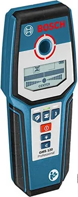
When drilling holes in walls it is essential to avoid contact with electrical cables, water or gas pipes, contained within. Use of a good quality live wire detector and hidden abscess locator is therefore recommended.
Only drill into structures when you are sure it is safe to do so.
Fixing hardware
It is highly recommended that all wall fixings be used where supplied and that the purpose of all hardware is fully understood.
In some cases, more AV equipment fixing hardware will be supplied to accommodate different models of equipment and set up configurations.
The installer must be satisfied that any supplied fixing hardware is suitable for each specific installation. If any fixing screws or included hardware are deemed not sufficient, for a safe installation, then please consult a professional or your local hardware store.
Hazard limitation
When routing cables take advantage of any built-in cable management features that the product might provide and ensure that all cables are properly routed and secure. Check to see that any moving aspect of the product can do so unhindered by any cabling. Do not block the sensor beam area of the XL No-Touch Mount.
Some products have moving parts and the potential to cause injury through the crushing or trapping of fingers or other body parts, exercise care and read all warnings.
Pay close attention to all moving parts, especially when assembling, installing and servicing. Immediately after installation, double check that the work done is safe and secure. Double check all necessary fixings are present and suitably tightened.
It is recommended that periodic inspections (not greater than 6 months apart) of the product and its fixing points are made, to ensure safety is maintained. If in doubt, consult a professional AV installer or other suitably qualified person.
Periodic Inspection Record:
| DATE | INSPECTED BY | LOCATION | SIGNED |
|---|
Installation tools required / CA PROP 65
California Prop 65 Information. Currently, we are not aware of any chemicals in this product that require warnings under California Proposition 65. However, as the list of chemicals constantly increases, we will maintain a web page on our internet site with any updates when they occur. For information on California Prop 65 please visit www.p65warnings.ca.gov
- Drill
- Drill bit
- Level
- Measuring tape
- Pencil
- Electric Wall Scanner
WARNING
ES
PureLink GmbH recomienda que un instalador de audio y video profesional u otra persona debidamente cualificada instalen este producto. PureLink GmbH, sus distribuidoresy concesionarios no se hacen cargo ni se responsabilizan de ningún daño o lesión provocados por una instalación inapropiada. Este producto se debe montar en una estructura adecuada y se debe utilizar soportando solamentre hasta el peso máximo indicado.
FR
PureLink GmbH recommande de confier I’installation de ce produit à un installateur AV professionnel ou à une autre personne dûment qualifiée. PureLink GmbH, ses distributeurs et ses revendeurs ne sauraient être tenus resounsables de tout dégât ou de toute blessure résultant d’ une installation incorrecte. Ce produit doit être monté sur un support approprité et utilisé dans la limite du poids maximum indiqué.
DE
PureLink GmbH empfiehlt, dass dieses Produkt durch einen qualifizierten AV-Techniker oder eine andere Person mit geeigneter Qualifikation installiert wird. PureLink GmbH, ihre Distributoren und Händler können nicht für durch fehlerhafte Montage verursachte Beschädigung oder Verletzung haftbar bzw. verantwortlich gemacht werden. Dieses Produkt muss auf eine geeignetem Untergrund montiert werden und darf nur bis zum angegebenen Höchstgewicht verwendet werden.
IT
PureLink GmbH consiglia di affidare I’installazione di questo prodotto a un installatore specializzato o ad altra persona adeguatamente qualificata. PureLink GmbH i suoi distributori e rivenditori non accettano alcuna responsabilità nei riguardi di eventuali danni o infortuni causati da un’errata installazione. Questo prodotto deve essere fissato a una struttura idonea e utilizzato unicamente sino al peso massimo indicato.
NL
PureLink GmbH adviseert om dit product te laten installeren door een professionele AV-installateur of andere hiervoor gekwalificeerde persoon. PureLink GmbH haar distributeurs en dealers zijn niet aansprakelijk of verantwoordelijk voor schade of letsel die is veroorzaakt door onoordeelkundige installatie. Dit product moet worden gemonteerd aan een geschikte constructie, waarbij het aangegeven maximum gewicht niet mag worden overschreden.
PT
A PureLink GmbH recomenda que a instalação deste produto seja efectuada por um instalador de AV instalador de AV profissional ou outra pessoa devidamente habilitada. A PureLink GmbH e os seus distribuidores e concessionários não são responsáveis por danos ou lesões causados por uma instalação incorrecta. Este produto tem de ser montado numa estrutura adequada e utilizado somente até ao peso máximo indicado.
PL
Firma PureLink GmbH zaleca, aby ten produkt był instalowany przez profesjonalnych instalatorów AV lub inny odpowiednio przeszkolony personel. Firma PureLink GmbH, jej dystrybutorzy i dealerzy nie ponoszą odpowiedzialności za uszkodzenia lub obrażenia ciała powstałe w wyniku nieprawidowej instalacji. Niniejszy produkt musi być zamontowany na odpowiedniej powierzchni, a podczas użytkowania nie wolno przekraczać podanego maksymalnego obciążenia.
CS
Společnost PureLink GmbH doporučuje provést instalaci tohoto produktu instalátora AV či jinak způsobilé osoby. Společnost PureLink GmbH, její distributoři a prodejci nenesou prostřednictvím odborného odpovědnost za škody nebo zranění způsobená nevhodnou instalací. Tento výrobek je nutno umístit do vhodné konstrukce a používat jen po uvedenou maximákní výšku.
RU
Warranty period : 3 Years
This PureLink product, delivered new, in the original carton to the original consumer purchaser, is warranted by PureLink against manufacturing defects in materials and workmanship for the warranty period above. This warranty begins on the original date of purchase. To receive warranty service, the purchaser must contact PureLink for problem determination and service procedures. Warranty service can only be performed by a PureLink authorized service centre. The original dated bill of sale must be presented upon request as proof of purchase to PureLink authorized service centre.
PureLink GmbH
PureLink GmbH
Note: Walls are built from different materials and require different wall bolts for best performance and safety. Please / General recommendations
- Start from the bottom corner (small) or central screen (large) of the video wall configuration.
- Height of screen determines center to center distance for next vertical mount location.
- Width of screen determines center to center distance for next horizontal mount location.
- Build Horizontallly first then add rows until all rows are completed.
3 3 4
1 1
1
2 2
21
Align the one common border before mounting the next screen
Align the two common borders before mounting the next screen
Check the wall structure being mounted to. Use a level to ensure the wall is flat and note areas of concern. Use washers, shims or spacers between the wall and the mount to create a flat surface for mounting. A flat mount will make adjustments much easier and faster when aligning screens.
Note: The PureLink GmbH XL No-Touch Mount is ONLY suitable for installation perpendicular to the floor in portrait or landscape orientation. It is NOT suitable for angled or overhead mounting. For angled mounting please see Soft-Touch Mount on www.purelink.de
Installation guide (for single screens go to Page 8)
For video walls, we suggest starting from a corner. Begin at the bottom left corner and add screens row by row, aligning them as you go. Before installation, make sure to center the depth and lateral micro-adjustments. This will make aligning the screens quicker and easier. If you’re working with a larger video wall, it’s recommended to start with the center screens. video walls it is advised to start with the center screens.
Step 3
Universal Controller Universal Controller
Connect the power supply to the control box and electrical socket
Only use the power supply provided. If not possible, contact PureLink GmbH to ensure the appropriate replacement is used. Note: The use of 3rd party power supplies will void warranty!
Note: Once the screens are installed, aligned and closed, to prevent accidental movement of the Mount or electrical interference/damage, ensure that Mount-dedicated power strips or power supply is turned off/unplugged, until next service appointment.
Connect the power supply to the control box
Step 4
150 mm
6 ’’
Light-Beam
The PureLink XL No-Touch Mount, allows the screen to move OUT and IN, without the need to touch the screen. Position the control wand approximately 150 mm/6” to the right of center of the mount (see below). The mount will slowly start to move OUT.
How to use Universal Controller to operate the Mount / Move Universal Controller with the Mounts
Movement
Once the Universal Controller is positioned below the light beam, the Mount will start moving. To keep the Mount moving, make sure you sync the Universal Controller with this movement. If you remove the controller from the right spot, the Mount will STOP.
To STOP the Mount, remove the Universal Controller from the light beam
The Mount will only move when the Universal Controller is in the light beam.
Once removed from light beam, the Mount will STOP
To CHANGE the Mounts DIRECTION, quickly SWIPE the Universal Controller underneath the light beam
You will hear a signal:
2 beeps: move IN
3 beeps: move OUT
After hearing the signal, position the Universal Controller again below the light beam to move the Mount in the chosen direction. When fully closed or open, it will not beep as it can only move one direction.
Position of the light beam
X = Depth of the screen
Y = 75mm
Z = X + Y + 10mm
Z* = Depth controller needs to be from front of screen to operate the Mount.
* some users mark the controller to show this distance for easier use
Step 5
For VESA 1000x600 Landscape For VESA 600x1000 Portrait
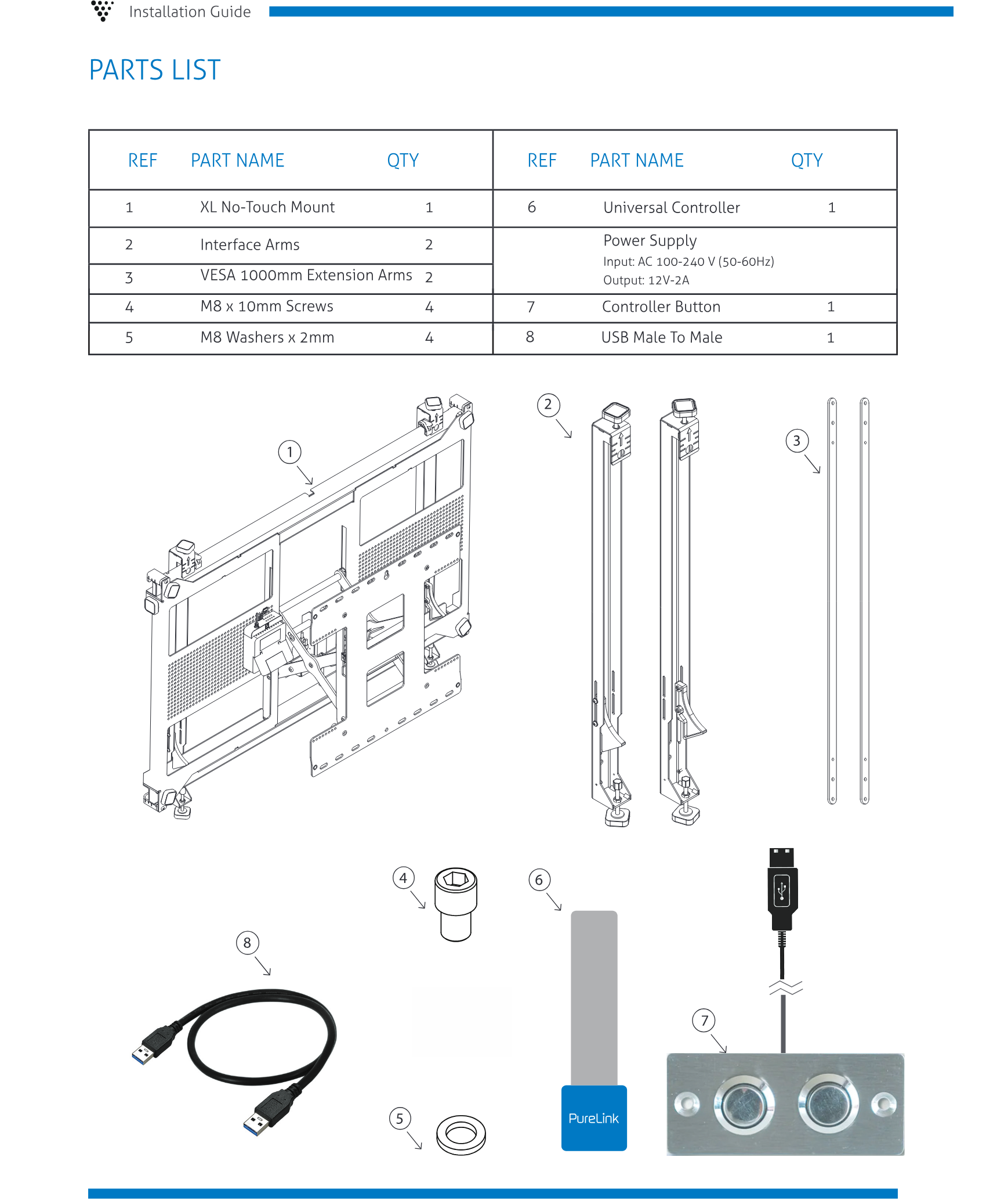
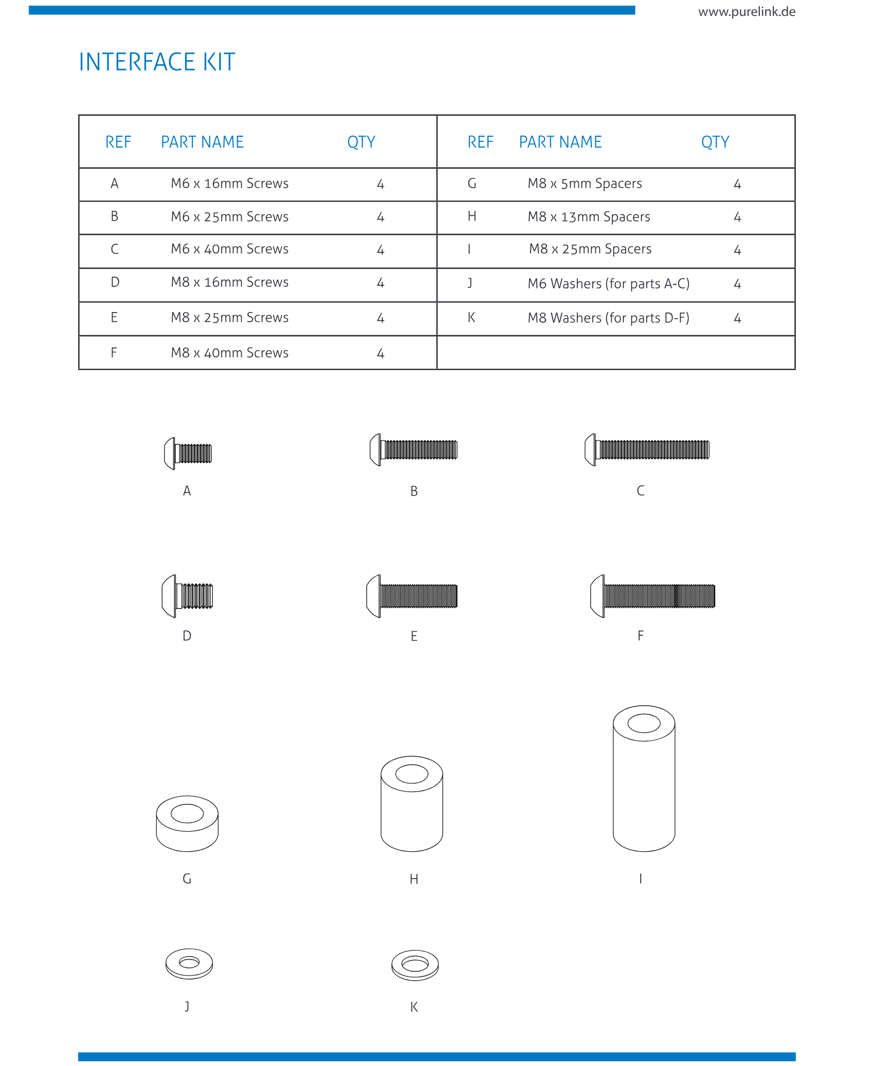
Attach the Interface Arms to the screen (Landscape or Portrait) The interface arms fit from VESA 300 x 300mm through 800 x 600mm. For 900 or 1000 mm VESA size, use supplied extension arms.
X Y
Z
Installation, connectivity and product data
Step 7 Make Adjustment (See below)
A: Height adjustment
B: Corner depth adjustment
C: Lateral macro adjust
D: Lateral micro adjustment
E: Locking handwheels (must be loosened for any adjustments)
Step 6 Connect screen to Mount
At slight angle, hook arms onto top of frame, then flatten screen onto Mount base until it clicks into position.
Height adjustment
Lateral Smart-Lock
Lateral micro adjustment
Tighten to secure (last step)
Corner depth
adjustment
A
C
B E
D
Lateral Smart-Lock
- unlock lateral Smart-Lock,
- slide screen into position,
- slide Smart-Lock to interface arm,
- lock Smart-Lock.
- After Smart-Lock is in position, the lateral micro adjustment can be used.
Lateral micro adjustment
Each time you add a screen to the video wall make needed adjustments.
*Note: Locking handwheels must be loosened before any adjustments can be made.
Once all adjustments are done, the locking handwheels can be tightened.
Locking handwheels
RECESS FLAT SCREEN INSTALLATION
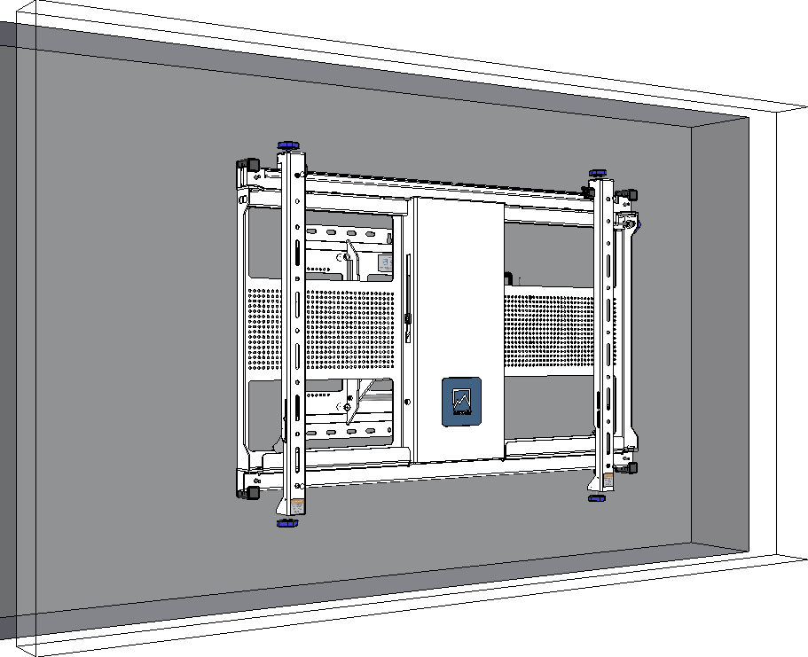
Step 1 Make a rectangular hole on the wall using the dimensions of the chosen screen by following the instructions below.
- Please ensure minimum gaps between the screen and four edges of the recessed box is 2mm and that corners and four angles are 90 degrees.
- Must use Electric Wall Scanner to locate the position of electric wires before drilling into the wall.
The hole on the wall (LxHxD)
L = Ls + X mm
H = Hs + Y mm
D = Ds + 100 mm
X, Y: Gap each corner
The mount
The screen (Ls x Hs x Ds)
Ls = Length
Hs = Height
Ds = Depth
The dimension of rectangular holes on the wall need to be created based on the screen’s dimensions.
Note: Some screen manufacturers do not put the VESA holes at the center of the screen backside. Therefore, you should locate the position of back wall plate and mark the drill holes with the following instruction.
Top of screen
Bottom of screen
Ls
Hs
Ds
H1
H3
H2
Y
X
Wall Hole
D
H
L
Center of wall hole
100
Mount space
Step 2 Locate the mount’s back wall plate by using tape ruler and bubble level.
Note: The VESA holes position of a monitor is pre-defined by the manufacturer.
- Must use Electric Wall Scanner to locate the position of electric wires before drilling into the wall.
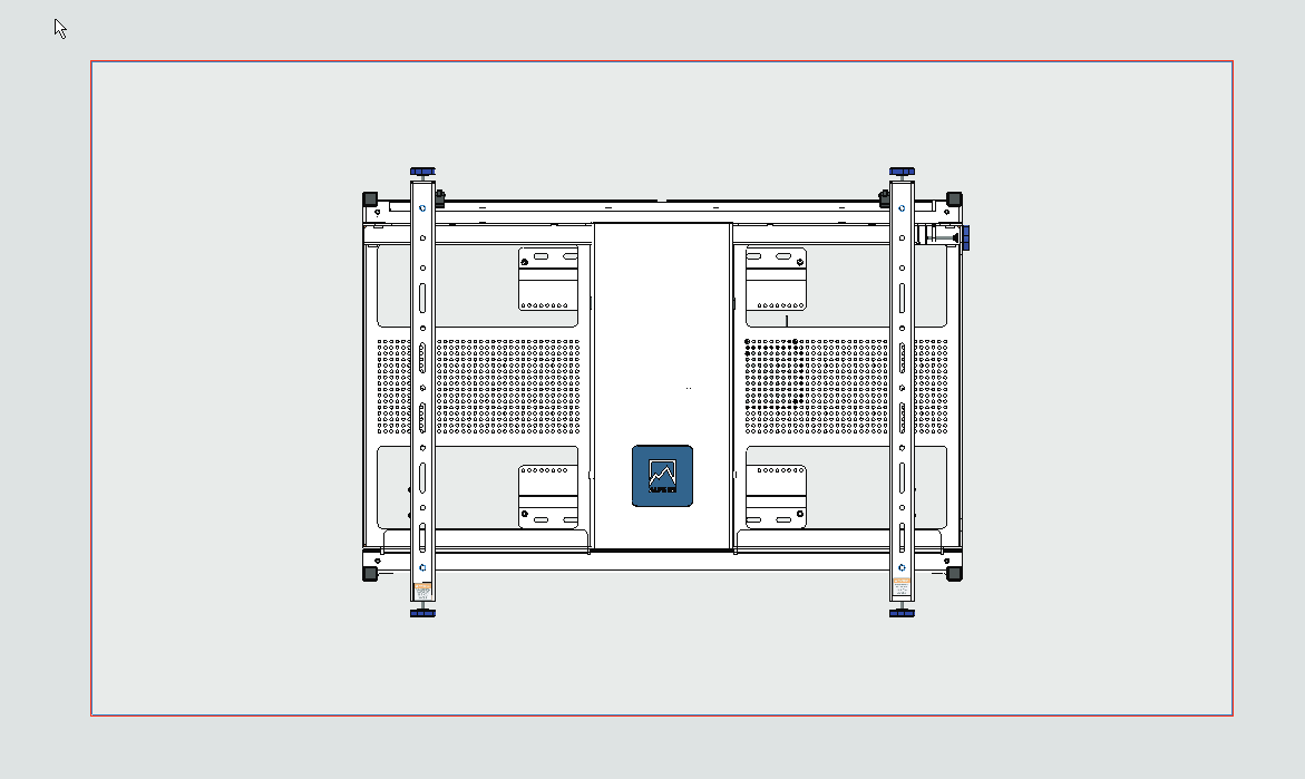
2.1 If H1=H3, the position of the mount will be in the middle of the recessed box (H1, H3: See on pages 15).
- Calculate and mark the rectangular box for the position of back wall plate by 3 dimensions as bellow A1, A2, B (Size of back wall plate HxW=468x480 mm) => Use measuring tape to confirm 3 dimension A1, A2, B are right
- Put the mount on the wall hole and mark the drill holes
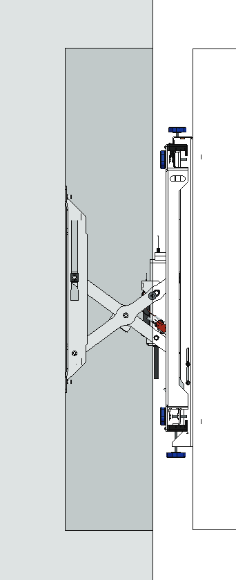
- Hang the screen and adjustment to fit with the wall hole (see pages 11-14).
Level
Top
Bottom
L
H
468 mm
480 mm
Center of wall hole=Center of screen
Note: Use at least 2 wall bolts (3 recommended) at Top and 2 wall bolts bottom of mount. Heavier screen should have 3 bolts at the topMeasure, mark and drill holesUse level to check alignment.Use an Electric Wall Scanner to locate the electrical wire if you want to drill a hole in the wall.Tighten all wall bolts (6 pcs recommended).
A1=(H-468)/2 mm
B=(L-480)/2 mm
B=(L-480)/2 mm
A2=(H-468)/2 mm
Closed Opened Front Top
Note: The picture above show only back wall plate for easy understanding, in fact there will be the whole mount
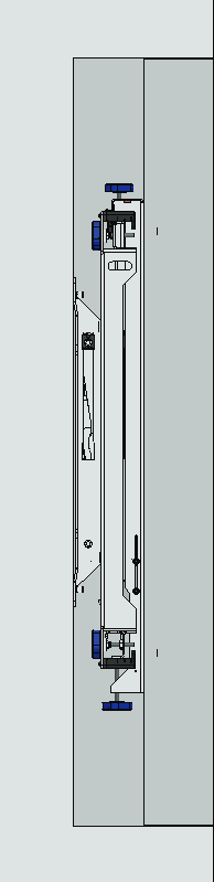
2.2 If H1<H3, the center of mount will be higher than the center of the recessed box. (H1, H3: See on pages 15).
- Calculate and mark the rectangular box for the position of back wall plate by 3 dimensions as bellow A1, A2, B (Size of back wall plate HxW=468x480 mm) => Use measuring tape to confrm 3 dimension A1, A2, B are right
- Put the mount on the wall hole and mark the drill holes
- Hang the screen and adjustment to fit with the wall hole (see pages 11-14).
Top
Bottom
L
H
468 mm
480 mm
Center of wall hole
A1=(H-468)/2 - (H3-H1) mm
B=(L-480)/2 mm
B=(L-480)/2 mm
A2=(H-468)/2 + (H3-H1) mm
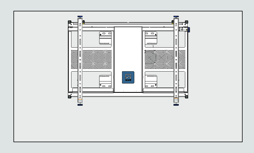
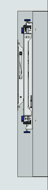
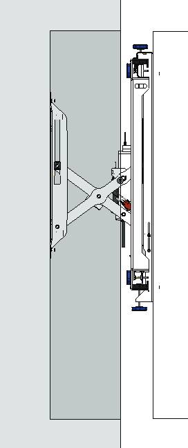
Closed Opened
Center of screen
H3-H1
Front
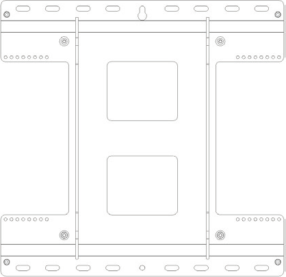
Top
2.3 If H1<H3, the center of mount will be lower than the center of the recessed box. (H1, H3: See on pages 15).
Top
Bottom
L
H
468 mm
480 mm
Center of wall hole
A1=(H-468)/2 + (H3-H1) mm
B=(L-480)/2 mm
B=(L-480)/2 mm
A2=(H-468)/2-(H3-H1) mm
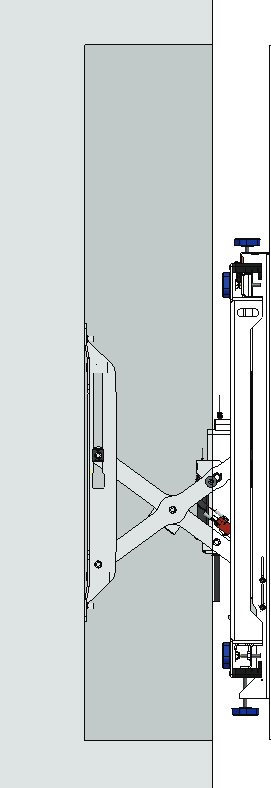
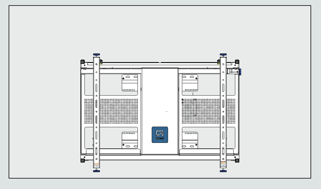
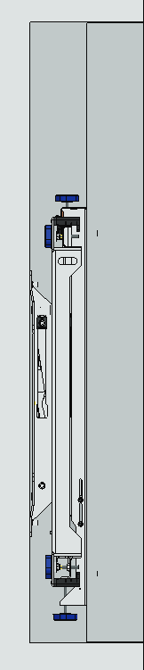
Closed Front Top Opened Center of screen H3-H1
CONNECTIVITY
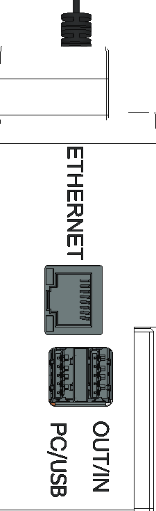
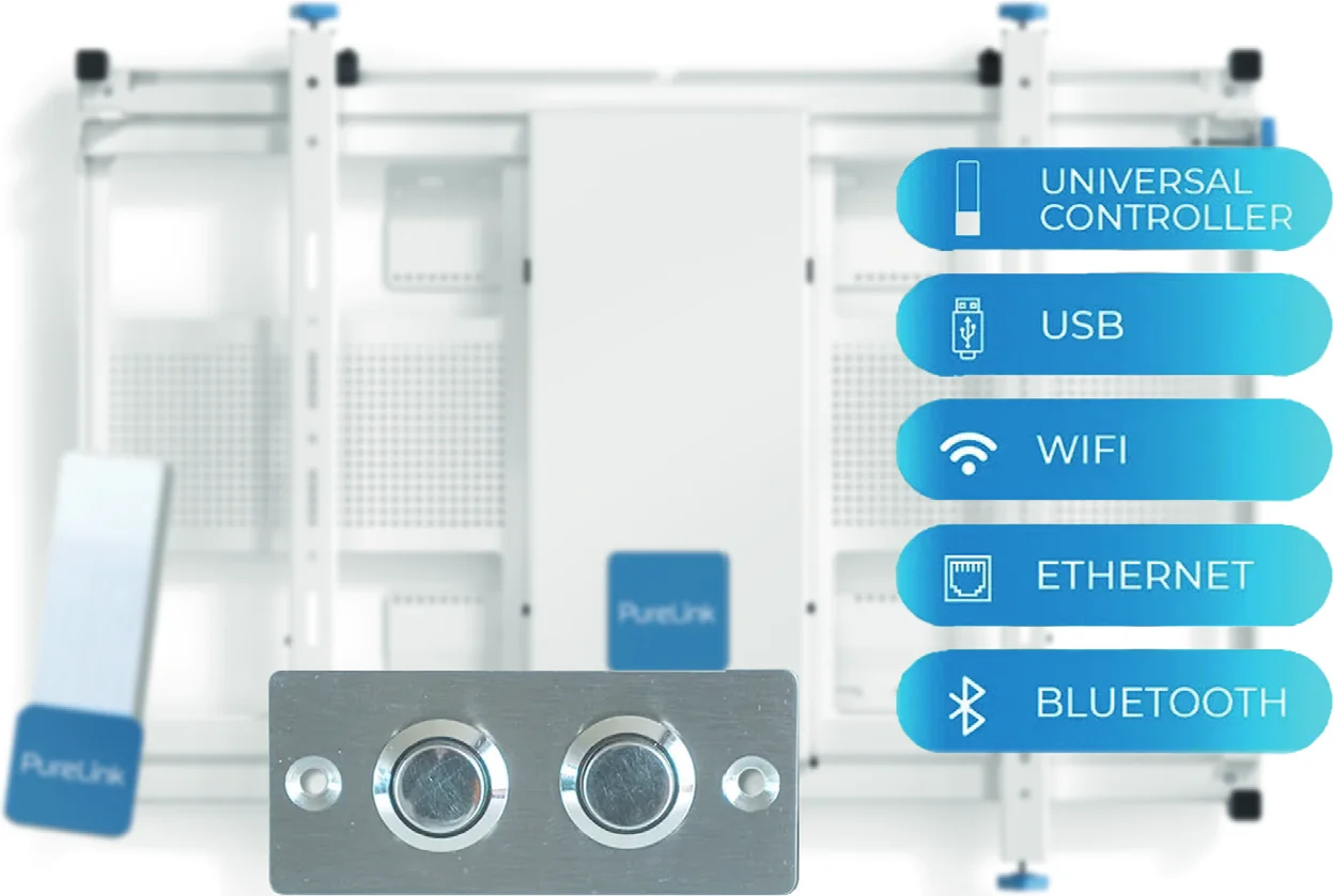
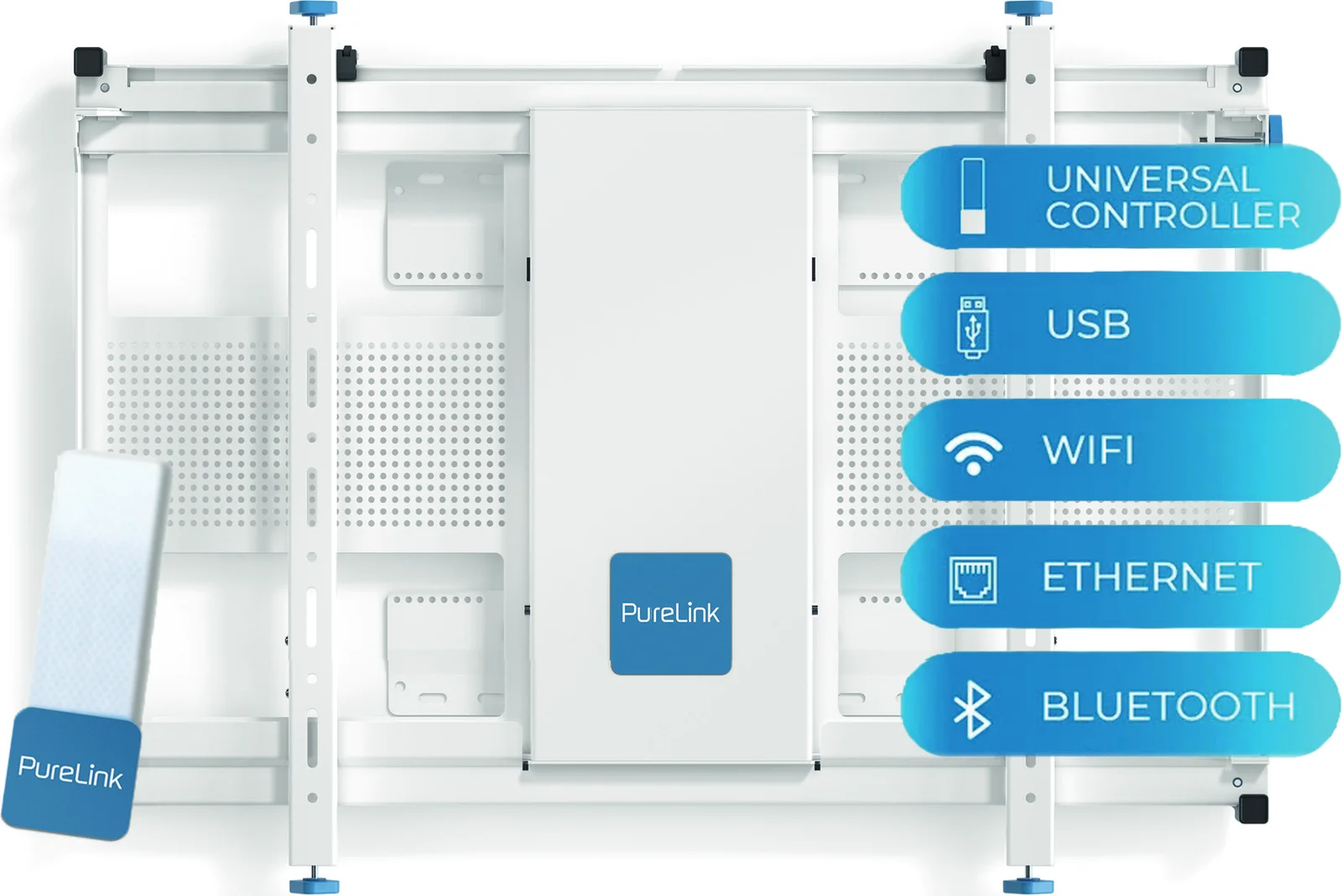
Control box
There are several different ways to control the mount
- Universal Controller
- USB
- Wifi
- Ethernet
- Bluetooth
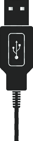
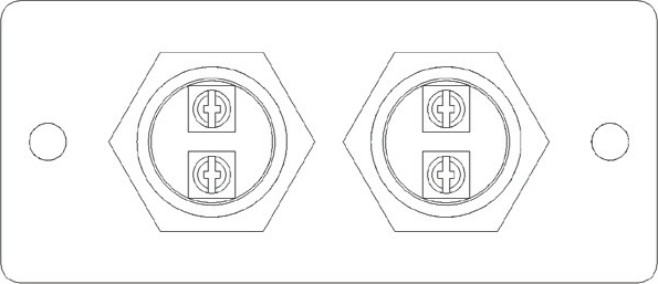
OUT/IN PORT
Secure the USB
cable in place by tightening it to the
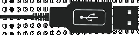
hole panel.
- Universal Controller To see how to control the mount using Universal Controller, go to pages 9-11.
- USB There are 2 ways to control the mount via USB Port (USB button and PC via USB port)
- Wifi
- Ethernet
- Bluetooth
USB
- USB Button 022 Plug USB connector into the right position (OUT/IN) 2022 Do cable management by using the hole panel 2022 Press the buttom to move the screen out/in
Important:
2022 Dont put the cable into the X-arm movement at center.
2022 Secure the USB cable in place on both sides
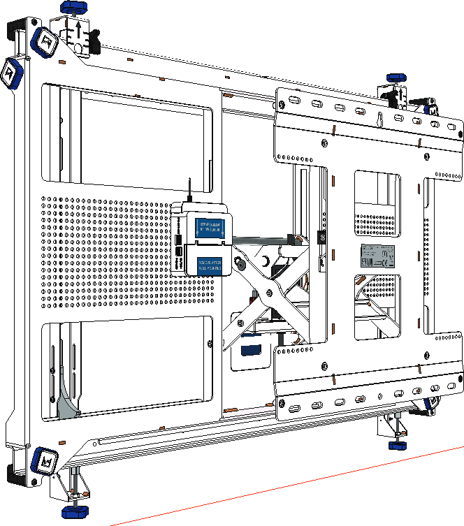
Note: How to wire the USB cable ?
2022 Dont use the 5V (Red) wire
WHITE
GREEN
GND (BLACK)
WHITE
GREEN
5V (RED), Dont use red wire (Remove)
GND (BLACK)
IN OUT
Control box
PC/USB Port
USB Male-to-male cable
PC
PC via USB Port
- Plug one connector of the USB cable Male to Male to PC/USB port.
- Plug the other connector side to PC
Control box
Mount 01 Mount 02
Control box
Wireless
Wireless Access point
INTERNET
LAPTOP PC DEVICES
SERVER
Need internet
Wifi
- The Mount connects to the Wireless Access Point via wireless connection.
- Wireless Access Point connects to the Internet Server.
- Laptop, PC or other devices connect to the Internet Server.
Caution: The Wireless Access Point needs to be as near the mount as possible
LAN cable LAN cable
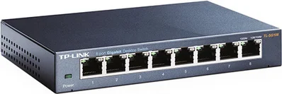
LAN cable
Switch
PC
Control box
Mount 01 Mount 02
Control box
Ethernet
Local Network Controller (Without internet)
- The Mount connects to the Switch
- The Switch connects to computers/laptops.
Note: Secure the LAN cable in place by tightening it to the hole panel.
Internet connection
- The Mount connects to the Switch
- The Switch connects to the Internet Server
- Laptop, PC or other devices connect to the Internet Server
Note: Scure the LAN cable in place by tightening it to the hole panel.
LAN cable LAN cable
Switch
INTERNET
LAPTOP PC DEVICES
SERVER
Need internet
Control box
Mount 01 Mount 02
Control box
Bluetooth
You can only connect one mount to one device at once.
2022 The Mount connects to smartphone via bluetooth.
Control box

Bluetooth
Smartphone
CONFIRMATION OF CE CONFORMITY
PureLink GmbH will not be held liable, nor provide any warranty for damage resulting from improper installation, assembly and use of the product, or failure to observe the operating instructions and/or safety instructions.
PureLink GmbH hereby declares that the device type WM-NT600 is in conformity with the Directives 2014/30/EU, 2019/1782/EU, 2011/65/EU, 2015/863/EU and 2014/35/EU
WEEE-Reg. No.: DE 93 847 290
According to the European WEEE Directive, electrical and electronic equipment may not be disposed of with household waste. As a consumer, you are obliged to return electrical and electronic equipment free of charge at the end of its service life to the public collection points set up for this purpose or to the point of sale. Details on this are regulated by the respective national law.
The symbol on the product, the instructions for use or the packaging refers to these regulations. Recycling old appliances in this way is an important contribution to the protection of our environment.
Motor Starts then stops
Controller not remaining in correct location - if the Controller is on the edge of the light beam, as the controller moves forward and backward with the moving mount, it can move out of the beam and stop. Move the controller left and right to check the beam location. Also note, the beam moves forwards and backwards with the mount, so move controller as the screen moves.
OR: Impact Detection is triggering. Impact detection exists but is variable depending on several factors including screen weight and size, where the impact occurs and if there is vibration. The motor will stop and when you place the controller back into the beam it will have reversed direction.
When first started and if not run for some time the motor might automatically calibrate its location. This is normal and once it has gone through a full cycle it will resume normal operation.
Check there is POWER. It is common to switch off or unplug power once set-up is finished, so check power is on. Check controller is in beam and move out of beam and back into beam.
Are handwheels at base of screen arms loosened?
If you are reaching the end of the range this will also occur. Make adjustments elsewhere to free up additional adjustment range.
PureLink GmbH
Von-Liebig-Str. 10 | 48432 Rheine
Germany
www.purelink.de | info@purelink.de
PureLink UK LTD.
Carpenter Court | 1 Maple Road | Bramhall
Stockport | Cheshire SK7 2DH
United Kingdom
Issues Solutions
- Motor moves slowly
- Motor does not start
- Handwheels are hard to turn
- Contact Us
Self help guide / PRODUCT DIMENSIONS
FRONT VIEW LANDSCAPE ADAPTOR
Max VESA 1000mm X 600mm
FRONT VIEW PORTRAIT ADAPTOR
VESA 600mm X 1000mm
Screen size > 82 22
18.4’’
468mm
FRONT SIDE VIEW OPEN SIDE VIEW CLOSED
29.5’’
748.8
39.9’’
1012.5 mm
39.4’’
1000 mm
29.5’’
748.8
mm
39.9”
1012.5 mm
11.4 ’’ (+/-0.3)
290 mm (+/-10mm)
3.8’’ (+/-0.3)
97.5 mm (+/-10mm)
35.4 ’’
900 mm
35.4 ’’
900mm
39.4 ’’
1000 mm
Legal & Compliance
Product identification
Models: VL-WM-NT600, VL-WM-NT600W – manual version 1.0
Trademarks and disclaimer
Product model and logo are trademarks. All other company and product names mentioned are trademarks of their respective owners. All rights reserved. No part of this publication may be copied or reproduced without prior written permission. We reserve the right to make changes to the device, packaging or manual and accept no liability for misprints.
Packaging
Dispose of packaging separately by material (paper/cardboard, plastics) via the local collection systems. Keep packaging material away from children – risk of suffocation. Packaging register LUCID: DE5958616449295.